2.2. “Motor” Page
The “Motor” configuration page is shown below in Fig. 7. The following sections describe the various available options and their appropriate settings for our gantry robot.
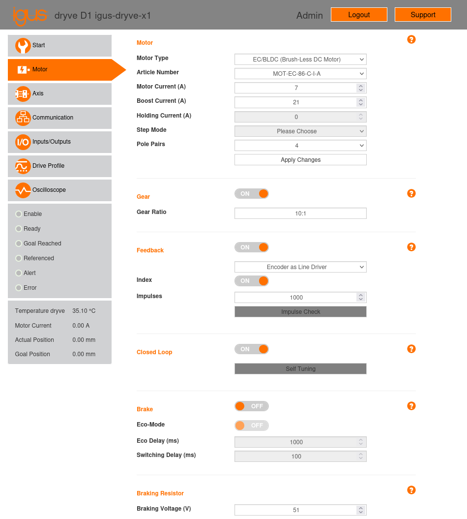
Fig. 7 “Motor” configuration page of the X1 motor controller.
2.2.1. Motor Configuration Summary
Table 1 below summarizes the configuration parameters for the motors in our gantry robot setup:
Parameter |
Value (X1/X2/Y) |
Value (Z) |
|---|---|---|
Motor |
||
Motor Type |
EC/BLDC |
ST |
Article Number |
MOT-EC-86-C-I-A |
MOT-AN-S-060-035-060-M-C-AAAC |
Motor Current (A) |
7 |
3.2 |
Boost Current (A) |
21 |
3.2 |
Pole Pairs |
4 |
N/A |
Step Mode |
N/A |
1/32 |
Step Angle (°) |
N/A |
1.8 |
Gear |
||
Gear Ratio |
10:1 |
N/A |
Feedback |
||
Type |
Encoder as a Line Driver |
Encoder as a Line Driver |
Index |
ON |
ON |
Impulses |
1000 |
500 |
Braking Resistor |
||
Braking Voltage (V) |
51 |
N/A |
2.2.2. Motor
Motor Type: The type of motor. Select “EC/BLDC (Brush-Less DC Motor)” for the brushless motors (X1, X2, Y) and “ST (Stepper Motor)” for the stepper motor (Z).
Article Number: For igus® motors, you can select the motor’s article number. In that case, parameters such as “Motor Current,” “Boost Current,” “Holding Current,” “Step Angle,” and “Pole pairs,” along with other settings in the “Gear,” “Feedback,” “Closed Loop,” “Brake,” and “Braking Resistor” sections, will be automatically populated with default values corresponding to the selected motor model.
In our gantry robot, we selected the article numbers of the motors used:
Brushless motors (X1, X2, Y): MOT-EC-86-C-I-A
Stepper motor (Z): MOT-AN-S-060-035-060-M-C-AAAC
Motor Current (A): Defines the maximum permissible continuous current for the motor during sustained movements, i.e.,excluding acceleration and deceleration phases (refer to the “Boost Current” option for those cases). Values can range from 0 A to 7 A.
Important
This parameter must be less than the maximum current that the power supply can provide, also considering any other loads it must supply power to.
In our gantry robot, the following values were set by default based on the motor article number:
Brushless motors (X1, X2, Y): 7 A
Stepper motor (Z): 3.2 A
Boost Current (A): Defines the maximum permissible current for the motor during acceleration and deceleration phases. During these periods, the maximum motor current set in the “Motor Current” parameter can temporarily increase up to the boost current value for a maximum duration of 2 seconds. Possible values range from the “Motor Current” parameter value up to 150 % (for stepper motors) or 300 % (for brushless motors) of the “Motor Current” parameter value.
Important
As with the previous parameter, this value must be less than the maximum current the power supply can provide, taking into account any additional loads.
In our gantry robot, the following values were set by default based on the motor article number:
Brushless motors (X1, X2, Y): 21 A (300% of motor current)
Stepper motor (Z): 3.2 A (100% of motor current)
Holding Current (A): Defines the current supplied to the motor when it is stopped. This setting is applicable only to open-loop stepper motors, otherwise the parameter will be disabled and grayed out.
In our gantry robot, the controller was configured for closed-loop operation, so this option is disabled.
Step Mode: This setting is applicable only to stepper motors, otherwise it will be disabled and grayed out. This parameter defines the microstepping technique to control the motor [Hug06, Wikipediacontributors23a]. Instead of moving the motor one full step at a time (1/1 step mode), microstepping divides each step into smaller fractions, enabling a greater number of intermediate positions. Available modes include “Auto,” 1/1 (full step), 1/2, 1/4, 1/8, 1/16, 1/32, and 1/64.
Smaller step sizes result in more precise positioning, improved movement stability, and reduced noise emission. However, the theoretical maximum speed will decrease. For example, a motor with a 1.8° step angle requires 200 steps to complete one revolution in 1/1 step mode. Generally, for a step angle \(\theta\) and 1/N step mode, \(360N/\theta\) steps are needed per revolution. Given that the controller can process step pulses with a minimum pulse period \(T\), the theoretical maximum motor speed in RPM will be \(60\theta/(360NT) = \theta/(6NT)\). Therefore, for a 1/N step mode, the theoretical maximum speed will be reduced by a factor of N compared to the theoretical maximum speed of the 1/1 mode.
The igus® dryve D1 documentation specifies a minimum step pulse period of 40 μs. However, the actual minimum period is smaller. Using a signal generator and an oscilloscope, we have verified that the actual minimum step pulse period supported by the igus® dryve D1 is 4 μs. Table 2 shows the steps per revolution and theoretical maximum speeds in RPM for each step mode, considering a 1.8° step angle and a 4 μs minimum step pulse period. Note that the speeds presented in the table are theoretical values calculated from the formula \(\theta/(6NT)\). In practice, stepper motors are not designed to reach high speeds. The maximum speed of a stepper motor depends on the motor model, but typically these motors do not exceed 1000 RPM.
In our gantry robot setup, we have set the step mode to 1/32 for the Z axis stepper motor.
Table 2 Step modes, steps per revolution, and theoretical maximum speeds in rpm, considering a step angle of 1.8° and a minimum step pulse period of 4 µs.¶ Step Mode
Steps per revolution
Maximum speed (rpm)
1
200
75000
1/2
400
37500
1/4
800
18750
1/8
1600
9370
1/16
3200
4680
1/32
6400
2340
1/64
12800
1170
Step Angle: This parameter, available only for stepper motors, defines the angle of a full motor step (e.g., 0.72°, 0.9°, 1.8°). It is a physical property of the motor itself and determines the number of full steps per revolution. For instance, a motor with a 1.8° step angle needs \(360/1.8 = 200\) full steps per revolution.
In our gantry robot, the stepper motor used has a step angle of 1.8°.
Pole Pairs: This parameter, available only for brushless motors, defines the number and arrangement of the motor coils. It is a physical property of the motor itself.
In our gantry robot, the brushless motors used have 4 pole pairs.
After completing the fields in this section, click the “Apply Changes” button.
2.2.3. Gear
If the motor includes a reduction gear, it can be configured in this section.
In our gantry robot:
Brushless motors (X1, X2, Y): We have selected a gear with a ratio of 10:1
Stepper motor (Z): No gear is used
2.2.4. Feedback
This section allows you to configure the parameters of the encoder connected to the controller. If an igus® motor was selected in the “Article Number” parameter within the “Motor” section, the parameters in this section will already be set to their correct values.
In our gantry robot setup, the following values were set by default based on the motor article number:
Brushless motors (X1, X2, Y)
Type: Encoder as a Line Driver
Index: ON
Impulses: 1000
Stepper motor (Z)
Type: Encoder as a Line Driver
Index: ON
Impulses: 500
Important
The “Impulse Check” button prompts the controller to automatically verify the number of encoder impulses. To do this, it rotates the motor by one revolution, even if the “enable” signal is not activated. Therefore, do not click this button if the motor cannot rotate freely.
2.2.5. Closed Loop
Through closed-loop control, the controller continuously compares the position information received from the encoder with the desired reference value and adjusts the motor based on this comparison. This continuous feedback enables error correction, maintaining the motor’s desired position, speed, or state, and more efficiently adapting to load variations. This results in precise and stable motor control, significantly reducing energy consumption and operating temperature.
We will set this option to “ON” for all motors in our gantry robot setup.
Important
For closed-loop control, the igus® dryve D1 internally uses two PI controllers to control current and speed, respectively, and a P controller for position control. The parameters of these controllers are shown on the “Oscilloscope” page (see Section 2.7.2). If the “Self Tuning” button in this section is pressed, the controller will attempt to automatically determine the optimal values for these parameters.
2.2.6. Brake
The igus® dryve D1 can control a holding brake. Since none of our motors are equipped with a brake, we will set this option to “OFF.”
2.2.7. Braking Resistor
This section applies only to brushless motors. When decelerating, these motors act as power generators. This can produce voltage peaks that exceed the applied load voltage, potentially damaging the controller, especially during rapid decelerations. To prevent damage, a braking resistor must be used to dissipate the excess energy generated. Therefore, it is essential that each controller driving a brushless motor is equipped with its own braking resistor.
Both the resistor’s value and its power dissipation capacity depend on the specific motor used. The controller manual provides detailed information on the appropriate values depending on the motor used. For our gantry robot we used a 3.3 Ω resistor, with a maximum power dissipation capacity of 100 W using a standard heatsink.
This section provides a single parameter, “Braking Voltage (V),” which sets the voltage threshold at which the braking resistor engages to dissipate excess energy. For safe operation, the controller incorporates a hysteresis of 1 V; thus, the braking resistor will activate when the motor voltage reaches the threshold voltage plus 1 V, and will deactivate when it drops to the threshold voltage minus 1 V.
The voltage threshold set in the “Braking Voltage” parameter should be slightly higher than the motor’s supply voltage. For instance, if the motor’s supply voltage is 24 V, a suitable threshold could be 26 V. If the motor’s supply voltage is 48 V, a suitable threshold could be 51 V. A value set too high could result in insufficient energy dissipation and trigger the “E09 Load Supply High” error (refer to the controller manual, Section 7: Alerts and Errors).
In our gantry robot setup, the brushless motors are powered at 48 V, so we set this parameter to 51 V.