3.8. LinuxCNC Configuration
As noted in Section 3.6.2, a LinuxCNC configuration comprises several files, requiring at least one INI file and one HAL file. The following sections detail the configuration of both file types, using the citic_gantry_robot configuration as an example.
3.8.1. INI Configuration
3.8.1.1. .ini Configuration File Format
An .ini file is a plain text file used for configuring applications and programs. It has a simple structure consisting of sections and key-value pairs. The basic syntax of an .ini file is as follows:
Sections: Sections serve to organize keys and values. Each section begins with its name enclosed in square brackets, followed by zero or more key-value pairs belonging to that section. The syntax for a section is:
[section_name]Keys and Values: Within each section, keys and their corresponding values can be defined. Keys are identifiers used to access associated values. The syntax for a key-value pair is:
key = value
Keys can contain letters and underscores (
_). Values can be text strings, integers, or floating-point numbers.Comments: Comments begin with a semicolon (
;) or a hash symbol (#). For example:; This is a comment # This is also a comment
3.8.1.2. citic_gantry_robot.ini Configuration File
Below are the different sections of the citic_gantry_robot.ini configuration file, with comments explaining the purpose of each parameter.
Note
Not all available parameters are specified in some sections. For a complete list of parameters and their documentation, consult the LinuxCNC user manual [lin23].
Note
Some parameters in INI files are used directly by LinuxCNC, but others are custom parameters added to be used in HAL files, as explained in Section 3.8.2.3. Parameters from the INI file can be accessed in HAL files using the syntax [<section>]<option>, where [<section>] is the section name in square brackets and <option> is the corresponding option name within that section.
EMC Section: General configuration.
 1[EMC]
 2# General configuration
 3
 4# Machine name, can be whatever you want.
 5# It will normally be displayed in the interface window.
 6MACHINE = CITIC Gantry Robot
 7
 8# Debug flags, with 0 no debug messages will be printed.
 9DEBUG = 0
10
11# Configuration version, for LinuxCNC 2.9 must be 1.1.
12VERSION = 1.1
DISPLAY Section: User interface configuration. The available options may depend on the specific user interface used. In this case, we are using the AXIS user interface.
14[DISPLAY]
15# Graphical interface configuration
16
17# Type of graphical interface to use.
18DISPLAY = axis
19
20# Coordinate system: RELATIVE or MACHINE.
21POSITION_OFFSET = MACHINE
22
23# Coordinates to display: COMMANDED or ACTUAL.
24POSITION_FEEDBACK = ACTUAL
25
26# Override the default cone/tool base size of .5 in the graphics display.
27CONE_BASESIZE = 2.0
28
29# Maximum feed override. A feed override of 2 means
30# 200% of the programmed feed rate.
31MAX_FEED_OVERRIDE = 2.000000
32
33# Image to show on the welcome screen.
34INTRO_GRAPHIC = linuxcnc.gif
35
36# Maximum time in seconds for the welcome screen.
37INTRO_TIME = 5
38
39# Default directory for G-code programs.
40PROGRAM_PREFIX = /home/gtec/linuxcnc/nc_files
41
42# Increments for moving the robot with manual control.
43INCREMENTS = 5mm 1mm .5mm .1mm .05mm .01mm .005mm
44
45# The coordinate value that will be displayed: COMMANDED or ACTUAL
46POSITION_FEEDBACK = ACTUAL
47
48# Default linear velocity with manual control, in units per second.
49DEFAULT_LINEAR_VELOCITY = 100.0
50
51# Maximum linear velocity allowed with manual control, in units per second.
52MAX_LINEAR_VELOCITY = 600.0
53
54# Minimum linear velocity allowed with manual control, in units per second.
55MIN_LINEAR_VELOCITY = 0.0
56
57# Text editor to use when clicking File -> Edit.
58EDITOR = mousepad
59
60# 3D view geometry in the preview window.
61GEOMETRY = XYZ
62
63# Update time in milliseconds.
64CYCLE_TIME = 100
65
66# PyVCP panel description file
67PYVCP = gui_panel.xml
68
69# File to open when starting LinuxCNC (optional).
70OPEN_FILE = ""
TASK Section: LinuxCNC task controller configuration. The task controller is responsible for communicating with the user interface, the motion planner, and the G-code interpreter. Currently,
milltaskis the only task controller available. For more information, consult the LinuxCNC user manual [lin23] and themilltaskman page, also available at http://linuxcnc.org/docs/devel/html/man/man1/milltask.1.html.74[TASK] 75# Task controller configuration 76 77# Task controller module, milltask. 78TASK = milltask 79 80# Execution period for milltask. 81CYCLE_TIME = 0.010
RS274NGC Section: RS274NGC (G-code) interpreter configuration.
84[RS274NGC]
85# RS274NGC interpreter configuration
86
87# Interpreter variables file.
88PARAMETER_FILE = linuxcnc.var
89
90# Startup codes for the interpreter.
91# The meaning of the currently set codes are:
92# - G21: set the unit system to use millimeters
93# - G40: turn tool compensation off
94# - G90: set distance mode to absolute positioning
95# - G94: set feed rate mode to units per minute
96# - G64 P0.025: configure path blending with a deviation tolerance of 0.025
97RS274NGC_STARTUP_CODE = G21 G40 G90 G94 G64 P0.025
EMCMOT Section: Motion controller configuration. The
EMCMOTandSERVO_PERIODparameters are not directly used by LinuxCNC but are used to configure the motion control module in the HAL file (see Section 3.8.2).100[EMCMOT] 101# Motion controller configuration 102 103# Motion controller module, motmod. 104# Not used by LinuxCNC directly, used in the HAL file. 105EMCMOT = motmod 106 107# Number of seconds to wait for the motion module 108# to confirm receipt of messages from the task module. 109COMM_TIMEOUT = 1.0 110 111# Servo thread period in nanoseconds 112# Not used by LinuxCNC directly, used in the HAL file. 113SERVO_PERIOD = 1000000
HAL Section: HAL configuration.
116[HAL]
117# Hardware Abstraction Layer (HAL) configuration
118
119# Add HAL user interface pins.
120HALUI = halui
121
122# HAL files to execute when starting LinuxCNC.
123# Can be specified multiple times.
124HALFILE = citic_gantry_robot.hal
125
126# HAL files to execute after loading the graphical interface.
127POSTGUI_HALFILE = gui_panel.hal
128
129# HAL files to execute when closing LinuxCNC.
130# SHUTDOWN = shutdown.hal
HALUI Section: HALUI (HAL-based user interface) configuration. The only available option is
MDI_COMMAND, which allows MDI commands to be executed via HAL signals. In our case we configure two commands which will be able to be executed via the PyVCP panel (see Section 3.8.4).133[HALUI] 134# HAL user interface 135 136# MDI_COMMAND can be specified multiple times. 137# To execute it use the pin halui.mdi-command-NN, 138# where NN is the command number. 139 140# Go to zero position 141MDI_COMMAND = G1 X0 Y0 Z0 F5000 142 143# Go to stop position 144MDI_COMMAND = G1 X5100 Y0 Z0 F5000
KINS Section: Kinematics configuration.
147[KINS]
148# Kinematics
149
150# Number of joints (motors).
151JOINTS = 4
152
153# Kinematics module
154# Not used by LinuxCNC directly, used in the HAL file.
155KINEMATICS = trivkins coordinates=XXYZ kinstype=BOTH
For machines with Cartesian geometries, such as gantry robots, where the movement of a joint is directly proportional to the movement of the axis, LinuxCNC includes the
trivkinskinematics module.The
trivkinsmodule accepts thecoordinatesparameter to specify the association of axis coordinate letters with the joint number. For example, with the parametercoordinates=XZ,JOINT_0will be assigned toXandJOINT_1toZ. In this parameter, the same axis letter can be specified multiple times, allowing multiple joints to be assigned to the same axis. In this case, it is also necessary to use thekinstype=Bparameter. For instance, with the parameterscoordinates=XXandkinstype=B, bothJOINT_0andJOINT_1will be assigned toX.For our gantry robot system, we use the parameters
coordinates=XXYZandkinstype=B, which means that the axes-joints mapping is the following:Xaxis →JOINT_0andJOINT_1Yaxis →JOINT_2Zaxis →JOINT_3
For more information about the
trivkinskinematics module, consult thekinsman page, also available at http://linuxcnc.org/docs/devel/html/man/man9/kins.9.html.APPLICATIONS Section: LinuxCNC allows applications to be launched at startup. These applications must be specified within the
APPLICATIONSsection using theAPPoption, which can be used multiple times. Applications will be launched either at the beginning, before the graphical interface starts, or after a delay specified by theDELAYoption.158[APPLICATIONS] 159# Additional applications. Can be specified multiple times. 160# APP=halscope 50000 161# APP=halscope 100000
TRAJ Section: Trajectory planner configuration.
164[TRAJ]
165# Trajectory planner configuration
166
167# Controlled axes. Possible values: X, Y, Z, A, B, C, U, V, W.
168# An axis can be specified more than once, e.g., XXYZ.
169COORDINATES = XXYZ
170
171# Units for linear axes.
172LINEAR_UNITS = mm
173
174# Units for rotary axes.
175ANGULAR_UNITS = degree
176
177# Maximum linear velocity, in units per second.
178MAX_LINEAR_VELOCITY = 600.0
179
180# Maximum linear acceleration, in units per second^2.
181MAX_LINEAR_ACCELERATION = 200.0
EMCIO Section: Input/output controller configuration. This controls input/output tasks such as coolant, tool changes, and emergency stops.
184[EMCIO]
185# Input/Output (I/O) controller configuration
186
187# Input/output controller module.
188EMCIO = io
189
190# Period at which EMCIO will run.
191CYCLE_TIME = 0.100
AXIS_<i> Section: Configuration for axis <i>. Possible values for <i> include
X,Y,Z,A,B,C,U,V, andW. Below we show the configuration for the X-axis. The configuration for the other axes is similar.Important
When configuring the robot’s limits (
MIN_LIMITandMAX_LIMITparameters), it is advisable to leave some margin beyond the desired workspace. If the robot is commanded to position itself at one of the limits, it can easily exceed that limit slightly. For example, if you want your robot to operate on the X-axis between X = 0 and X = 200, you could configureMIN_LIMIT = -5andMAX_LIMIT = 205.194[AXIS_X] 195# X axis configuration 196 197# Note: The X axis motors (Igus MOT-EC-86-C-I-A) have a a maximum speed of 198# 3000 rpm and a reduction gear with ratio 0.1. The X axis moves 144 mm/rev, 199# therefore the maximum speed is: 144 * 0.1 * 3000 / 60 = 720.0 mm/s. 200 201# Maximum axis velocity, in units per second. 202MAX_VELOCITY = 600.0 203 204# Maximum axis acceleration, in units per second^2. 205MAX_ACCELERATION = 200.0 206 207# Minimum limit for the axis, in machine units. 208MIN_LIMIT = -5.0 209 210# Maximum limit for the axis, in machine units. 211MAX_LIMIT = 5300.0
JOINT_<n> Section: Configuration for joint (motor) <n>, where <n> is the joint number, ranging from 0 to (<num_joints> \(-\) 1). The value of <num_joints> is set in the
JOINTSoption of theKINSsection.Important
Both the joint and axis configurations include
MAX_VELOCITY,MAX_ACCELERATION,MIN_LIMIT, andMAX_LIMITparameters. When the robot is not homed, LinuxCNC uses the parameters from the joint sections, however, once the robot is homed, it uses the parameters from the axis sections.The following code shows the configuration of joint 0, which corresponds to the X1 brushless motor. The parameters specified below the comments starting with “Custom configuration:” are not directly used by LinuxCNC, they are used to configure the motor parameters in the HAL file (see Section 3.8.2).
257[JOINT_0]
258# X1 motor configuration
259
260# Motor type, LINEAR or ANGULAR.
261TYPE = LINEAR
262
263# Maximum following error, in machine units.
264FERROR = 10
265
266# Maximum following error at very slow speeds.
267MIN_FERROR = 1
268
269# Maximum motor velocity, in units per second.
270MAX_VELOCITY = 50.0
271
272# Maximum motor acceleration, in units per second^2.
273MAX_ACCELERATION = 20.0
274
275# Minimum motor limit, in machine units.
276MIN_LIMIT = -5.0
277
278# Maximum motor limit, in machine units.
279MAX_LIMIT = 5300.0
280
281# Position to which the joint will move when completing the homing process.
282HOME = 0
283
284# Used to define the 'home all' sequence.
285# Note: the homing of the X joints must be synchronized, so we set their
286# HOME_SEQUENCE options to -1. For more details check the LinuxCNC manual.
287HOME_SEQUENCE = -1
288
289# Home switch position, in machine units.
290HOME_OFFSET = -15
291
292# Initial homing search velocity, in units per second.
293HOME_SEARCH_VEL = -25
294
295# Final homing search velocity, in units per second.
296HOME_LATCH_VEL = -5
297
298# Final homing velocity, in units per second.
299HOME_FINAL_VEL = 10
300
301# Ignore limit switches during homing.
302# Must be set to YES when using the same switch for limits and homing.
303HOME_IGNORE_LIMITS = YES
304
305# The switch is shared with another joint.
306HOME_IS_SHARED = 0
307
308# Use encoder index pulse for homing.
309HOME_USE_INDEX = NO
310
311# *****************************************
312# Custom configuration: +-10V analog output
313# *****************************************
314
315# Maximum velocity in units per second.
316ANALOGOUT_MAXLIM = 720
317
318# Minimum velocity in units per second.
319ANALOGOUT_MINLIM = -720
320
321# Analog output scale. Vout = 10 * velocity / ANALOGOUT_SCALE.
322# Maximum velocity in units per second that the motor can reach.
323# Important: must be set to the same maximum speed configured
324# in the motor controller in the drive profile section.
325# Note: we set it negative to reverse the direction of the movement.
326ANALOGOUT_SCALE = -720
327
328# *****************************
329# Custom configuration: Encoder
330# *****************************
331
332# Encoder scale. ENCODER_SCALE = counts / Position.
333# The encoder does 1000 ppr (4000 cpr). The motor (Igus MOT-EC-86-C-I-A)
334# has a reduction gear with ratio 0.1 and moves the axis at 144 mm/rev.
335# Therefore the encoder scale is 4000 / (144 * 0.1) = 277.7778.
336# Note: we set it negative to reverse the direction of the movement.
337ENCODER_SCALE = -277.7778
338
339# *************************
340# Custom configuration: PID
341# *************************
342
343P = 40
344I = 5
345D = 0
346FF0 = 0
347FF1 = 1
348FF2 = 0.01
349BIAS = 0
350DEADBAND = 0
351MAX_OUTPUT = 0
The following code shows the configuration of joint 3, which corresponds to the Z stepper motor. As before, the parameters specified below the comments starting with “Custom configuration:” are not directly used by LinuxCNC, they are used to configure the motor parameters in the HAL file (see Section 3.8.2). These parameters differ from the previous ones because now a stepper motor is used.
546[JOINT_3]
547# Z motor configuration
548
549# Motor/axis physical data:
550# - Motor step angle: 1.8°
551# - Z axis displacement: 4 mm/rev
552# Configured operating parameters:
553# - Motor step mode: 1/32
554# - Step pulse period: 10us
555#
556# Therefore, the theoretical maximum speed of the Z axis is:
557# 1 / (10e-6) * 4 / (16*360/1.8) = 125 mm/s = 125 * 60 / 4 rev/min = 1875 rev/min
558#
559# In practice the maximum speed is approximately 1200 mm/min =
560# 20 mm/s = 300 rev/min. See engine specifications: the torque after
561# 100 rev/min drastically reduces when increasing rev/min.
562
563# Motor type, LINEAR or ANGULAR.
564TYPE = LINEAR
565
566# Maximum following error, in machine units.
567FERROR = 1
568
569# Maximum following error at very slow speeds.
570MIN_FERROR = 1
571
572# Maximum motor velocity, in units per second.
573MAX_VELOCITY = 20.0
574
575# Maximum motor acceleration, in units per second^2.
576MAX_ACCELERATION = 80.0
577
578# Minimum motor limit, in machine units.
579MIN_LIMIT = -1050.0
580
581# Maximum motor limit, in machine units.
582MAX_LIMIT = 5
583
584# Position to which the joint will move when completing the homing process.
585HOME = 0
586
587# Used to define the 'home all' sequence.
588HOME_SEQUENCE = 3
589
590# Home switch position, in machine units.
591HOME_OFFSET = 15
592
593# Initial homing search velocity, in units per second.
594HOME_SEARCH_VEL = 10
595
596# Final homing search velocity, in units per second.
597HOME_LATCH_VEL = 1
598
599# Final homing velocity, in units per second.
600HOME_FINAL_VEL = -10
601
602# Ignore limit switches during homing.
603# Must be set to YES when using the same switch for limits and homing.
604HOME_IGNORE_LIMITS = YES
605
606# The switch is shared with another joint.
607HOME_IS_SHARED = 0
608
609# Use encoder index pulse for homing.
610HOME_USE_INDEX = NO
611
612# *******************************************
613# Custom configuration: Step signal generator
614# *******************************************
615
616# Minimum duration of stable direction signal before a step begins, in nanoseconds.
617DIRSETUP = 10000
618
619# Minimum duration of stable direction signal after a step ends, in nanoseconds.
620DIRHOLD = 10000
621
622# Duration of the step signal, in nanoseconds.
623STEPLEN = 5000
624
625# Minimum interval between step signals, in nanoseconds.
626STEPSPACE = 5000
627
628# Note: for a STEPLEN and a STEPSPACE, the maximum theoretical speed when
629# using a 1/32 step mode is: 10^9/(STEPLEN+STEPSPACE) * 4 * 1.8 / (32 * 360)
630# For STEPLEN = 5000 and STEPSPACE = 5000 this is:
631# 10^9/10000 * 4 * 1.8 / (32 * 360) = 62.5 mm/s
632
633# Converts from counts to position units. position = counts / STEP_SCALE.
634# The Z axis moves at 4 mm/rev, the motor has a 1.8° step, and the Igus Dryve
635# controller is configured to use 1/32 step mode. Therefore, the step scale is
636# (32 * 360/1.8) / 4 = 1600.
637STEP_SCALE = -1600
638
639# Maximum acceleration, in units per second^2.
640STEPGEN_MAXACCEL = 100
641
642# *****************************
643# Custom configuration: Encoder
644# *****************************
645
646# Encoder scale (ENCODER_SCALE = counts / Position).
647# The encoder does 500 ppr (2000 cpr), and the Z axis moves at 4 mm/rev.
648# Therefore, the encoder scale is 2000 / 4 = 500.
649ENCODER_SCALE = -500
650
651# *************************
652# Custom configuration: PID
653# *************************
654
655P = 5
656I = 0.25
657D = 0
658FF0 = 0
659FF1 = 1
660FF2 = 0
661BIAS = 0
662DEADBAND = 0
663MAX_OUTPUT = 0
3.8.2. HAL Configuration
HAL is a fundamental component of LinuxCNC, serving as an interface between the machine’s software and hardware. It provides the infrastructure for communication among the system’s numerous software and hardware components. The HAL layer is composed of components that:
Are interconnected, processing incoming data and providing outputs to other components (e.g., the motion planning algorithm instructs the motors on their movement).
Possess the ability to communicate with hardware.
Always run periodically in one of the following ways:
As real-time components, either with an execution frequency of a few microseconds (e.g., to advance a stepper motor or read an encoder) or with a frequency less than one millisecond (e.g., to adjust the planning of subsequent movements to complete a G-code instruction).
As non-real-time user-space components, which can be interrupted or delayed if the rest of the system is busy or overloaded.
The HAL components included with LinuxCNC are listed in the user manual [lin23], also available at http://linuxcnc.org/docs/stable/html/hal/components.html. Additionally, each component has its own man page.
3.8.2.1. Basic Concepts
Pins and Signals: HAL is based on the same principles used to design electrical circuits and hardware systems, employing “pins” and “signals” to represent the flow of data between HAL modules or components. In summary:
Pins can carry boolean, float, and signed or unsigned integer values.
Pins have a direction: input (IN), output (OUT), or input/output (I/O).
A signal identifies a connection between pins.
Fig. 29 from the LinuxCNC documentation [lin23] illustrates the concepts of components, pins, and signals in HAL. In the figure, pin
pin3-outofcomponent.0connects to pinspin3-inandpin4-inofcomponent.1(via thesignal-redsignal), and pinpin1-outofcomponent.1connects to pinpin1-inofcomponent.0(via thesignal bluesignal).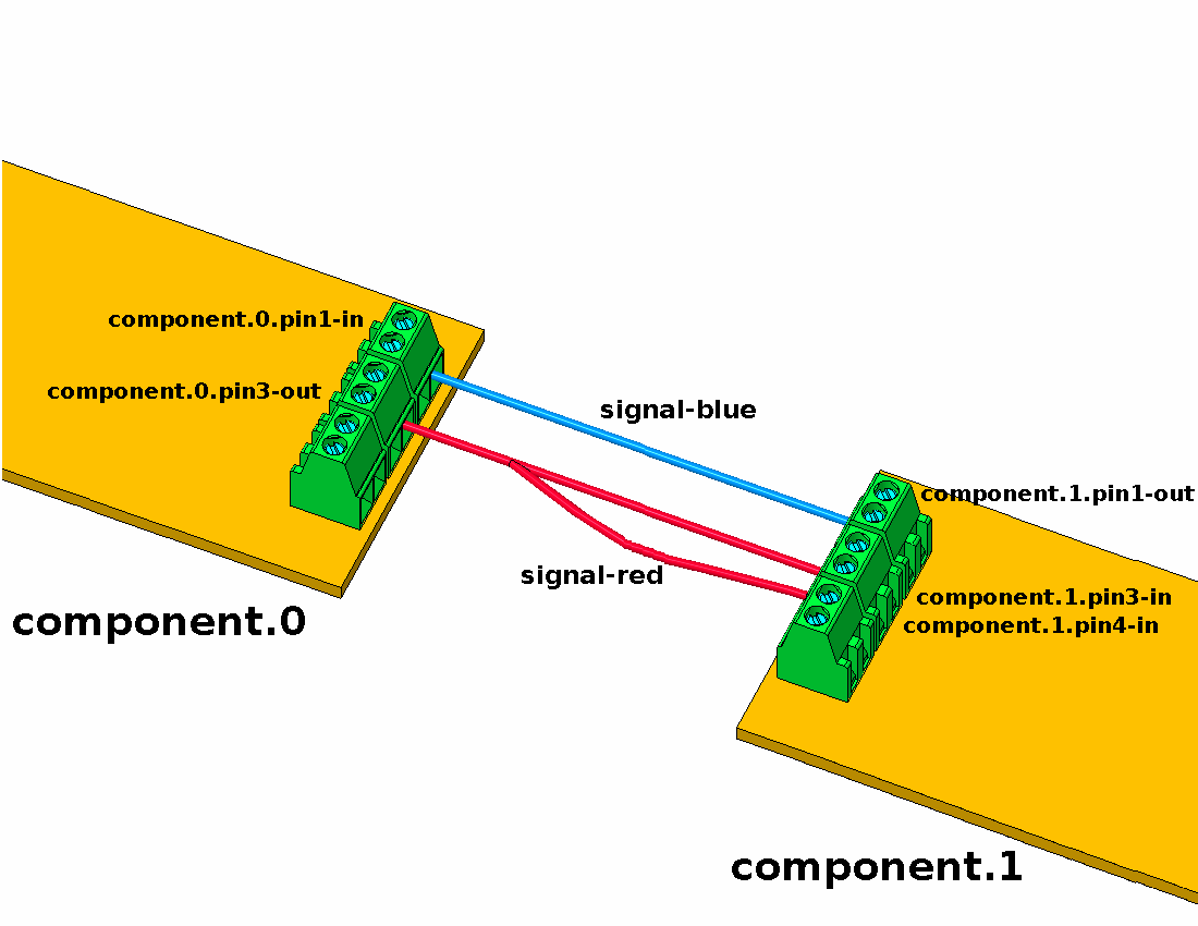
Fig. 29 HAL Concept — Connection as electrical circuits. Source: LinuxCNC documentation [lin23].
Parameters: HAL components can have parameters, which are input or output settings not connected to any other component. There are two types of parameters:
Input parameters: Values that the user can adjust and that remain fixed once configured.
Output parameters: Values that cannot be adjusted by the user. They allow for internal signals to be monitored.
Functions: Each HAL component has one or more functions that must be executed to perform the component’s task. For these functions to be executed, they must be added to a thread.
Threads: Threads enable HAL component functions to be executed at specific time intervals. When a thread is created, the time interval at which its assigned functions will be executed is specified. Subsequently, the functions of the HAL components can be added to the thread to be executed in order at the thread’s defined time interval.
3.8.2.2. Interaction with HAL and Commands
HAL does not interact directly with the user. LinuxCNC provides various interfaces to configure or interact with HAL:
From
.halfiles.From the command line using the
halcmdcommand.From Python scripts.
From C/C++ programs.
Configuration or interaction with HAL using any of these interfaces is performed through commands. The complete list of commands is detailed in the halcmd man page, also available at http://linuxcnc.org/docs/html/man/man1/halcmd.1.html. The most relevant commands are:
Note
Generally, each command must be specified on a single line. If a command needs to be split across multiple lines, a backslash (\) character can be used to indicate that the line continues to the next. The backslash must be the last character before the new line.
loadrt: Loads a HAL real-time component into the system. The basic syntax of theloadrtcommand is:loadrt <component> <options>
where
<component>is the name of the component and<options>are the component options. For example:loadrt mux4 count=1
addf: Adds a function to a real-time thread. The syntax of theaddfcommand is:addf <function> <thread>
where
<function>is the name of the function and<thread>is the thread to which it will be added. For example:addf mux4.0 servo-thread
loadusr: Loads a non-real-time HAL component into the system. Non-real-time components are separate processes that can optionally communicate with other HAL components via pins and parameters. Real-time components cannot be loaded into non-real-time space. The syntax of theloadusrcommand is:loadusr [<flags>] <command>
where
<command>is the program command to be executed and<flags>can be one or more of the following options:-i: Ignore the program’s return value (with-w).-w: Wait for the program to finish.-W: Wait for the component to be ready. It is assumed that the component will have the same name as the first argument of the command.-Wn <name>: Wait for the component to be ready and assign it the name<name>. This is only applicable if the component has the-noption to assign a name.
For example:
loadusr -Wn spindle gs2_vfd -n spindle
net: Creates a connection between a signal and one or more pins. The syntax is as follows:net <signal> <pin>
where
<signal>is the name of the signal and<pin>is the name of a pin. If the signal does not exist, a new signal is created. The command also allows the use of the words<=,=>, and<=>, separated by a space from the pin names, to indicate the direction of the signals between pins. These words are ignored by the command and merely serve to facilitate readability.The following rules must be met to connect a pin to a signal:
An input (IN) pin can always be connected to a signal.
An input/output (I/O) pin can be connected unless there is an output (OUT) pin on the signal.
An output (OUT) pin can be connected only if there are no other output (OUT) or input/output (I/O) pins on the signal.
The same signal name can be used in multiple
netcommands to connect additional pins, provided the above rules are respected.Examples:
net home-x joint.0.home-sw-in <= parport.0.pin-11-in
where
home-xis the signal name,joint.0.home-sw-inis an input (IN) pin,<=is the optional direction arrow (ignored by the command), andparport.0.pin-11-inis an output (OUT) pin.This example can also be equivalently defined in HAL by two
netcommands:net home-x <= parport.0.pin-11-in net home-x => joint-0.home-sw-in
Note
As seen in this example, although the second pin’s name has the
-insuffix, HAL treats it as an output pin. Therefore, when configuring pin connections in HAL, always refer to how the pin is configured in HAL, not just its name.net xStep stepgen.0.out => parport.0.pin-02-out parport.0.pin-08-out
where
xStepis the signal name,stepgen.0.outis an output pin, andparport.0.pin-02-outandparport.0.pin-08-outare input pins.This example can also be defined in HAL by two
netcommands as follows:net xStep <= stepgen.0.out net xStep => parport.0.pin-02-out parport.0.pin-08-out
setp: Sets the value of a pin or parameter. Valid values depend on the pin or parameter’s data type. The syntax of this command is:setp <name> <value>
where
<name>is the name of the pin or parameter and<value>is the value to which it is to be set. The command will fail if<name>does not exist as a pin or parameter, if it is a read-only parameter, if it is an output (OUT) pin, if it is a pin that is already connected to a signal, or if<value>is not a valid value for the pin or parameter’s data type.sets: Sets the value of a signal. The syntax is:sets <signal> <value>
where
<signal>is the name of the signal and<value>is the value to which it is to be set. The command will fail if<signal>does not exist as a signal, if the signal is already connected to an output (OUT) pin, or if<value>is not a valid value for the signal’s data type.unlinkp: Unlinks a pin from its connected signal. The syntax of the command is:unlinkp <name>
where
<name>is the name of the pin. If the pin does not have a connected signal, nothing happens. The command will fail if<name>does not exist as a pin.
3.8.2.3. .hal File Format
A .hal file is a plain text file containing HAL commands. Comments can be included by starting lines with the hash symbol (#). Options from the .ini file can be accessed with the syntax [<section>]<option>, where [<section>] is the section name in square brackets and <option> is the corresponding option name within that section.
3.8.2.4. citic_gantry_robot.hal Configuration File
As noted in Section 3.6.2, a LinuxCNC configuration includes at least one .ini file and one .hal file. Below we show several fragments of the citic_gantry_robot.hal configuration file, the main HAL file for the citic_gantry_robot.ini file as detailed in Section 3.8.1. Unlike the .ini format, the .hal format does not have a section syntax, however, for clarity, the file is presented below divided into different parts.
Note
The documentation of the different HAL components and its pins can be found in the LinuxCNC man pages [lin23]. The components and pins available in the running system can be also explored using the halcmd or halshow tools. See Section 3.8.3 for more details.
Load modules, add functions to threads, and other initial configurations:
  1# -----------------------------------------------------------------------------
  2# Modules
  3# -----------------------------------------------------------------------------
  4
  5# **********
  6# Kinematics
  7# **********
  8
  9loadrt [KINS]KINEMATICS
 10
 11
 12# **************
 13# Motion control
 14# **************
 15# Note that with the option "servo_period_nsec" the module will create a
 16# thread called "servo-thread".
 17
 18loadrt [EMCMOT]EMCMOT servo_period_nsec=[EMCMOT]SERVO_PERIOD num_joints=[KINS]JOINTS
 19
 20# Add motion functions to the "servo-thread" thread
 21addf motion-command-handler servo-thread
 22addf motion-controller servo-thread
 23
 24
 25# ********
 26# Hostmot2
 27# ********
 28# hostmot2 is the control module for MESA boards
 29
 30loadrt hostmot2
 31
 32
 33# *******
 34# hm2_eth
 35# *******
 36# hm2_eth is the low-level controller for MESA boards with Ethernet
 37# (Mesa Electronics Ethernet Anything IO boards)
 38
 39loadrt hm2_eth board_ip="192.168.1.121" config="num_encoders=4 num_pwmgens=0 num_stepgens=1"
 40
 41# Set the watchdog timeout for the MESA 7I96S board
 42setp hm2_7i96s.0.watchdog.timeout_ns 5000000
 43
 44# Configure the DPLL (digital phase locked loop) of the hostmot2 module
 45setp hm2_7i96s.0.dpll.01.timer-us -100
 46setp hm2_7i96s.0.stepgen.timer-number 1
 47setp hm2_7i96s.0.encoder.timer-number 1
 48
 49# Add functions to the "servo-thread" thread
 50addf hm2_7i96s.0.read servo-thread
 51addf hm2_7i96s.0.write servo-thread
 52
 53
 54# **************
 55# Classic Ladder
 56# **************
 57loadrt classicladder_rt
 58
 59addf classicladder.0.refresh servo-thread
 60
 61# load classic ladder project
 62loadusr classicladder myladder.clp --nogui
 63
 64
 65# ***
 66# pid
 67# ***
 68# We create a PID controller for each motor
 69
 70loadrt pid names=pid.x1,pid.x2,pid.y,pid.z
 71
 72addf pid.x1.do-pid-calcs servo-thread
 73addf pid.x2.do-pid-calcs servo-thread
 74addf pid.y.do-pid-calcs servo-thread
 75addf pid.z.do-pid-calcs servo-thread
 76
 77
 78# ***********
 79# estop_latch
 80# ***********
 81# module to handle the emergency stop
 82
 83loadrt estop_latch
 84addf estop-latch.0 servo-thread
 85
 86
 87# *******
 88# oneshot
 89# *******
 90# one-shot pulse generator
 91
 92loadrt oneshot names=oneshot.analog-start,oneshot.reset
 93
 94setp oneshot.analog-start.width 0.1
 95setp oneshot.reset.width 0.1
 96
 97addf oneshot.analog-start servo-thread
 98addf oneshot.reset servo-thread
 99
100# *****
101# logic
102# *****
103# Component providing configurable logic functions
104
105# We define the following functions:
106# - logic.error: OR gate with 4 inputs
107# - logic.alert: OR gate with 4 inputs
108# - logic.fault: OR and NOR gates with 3 inputs
109# - logic.analog-enable: AND gate with 3 inputs
110# - logic.analog-motors-start: AND gate with 3 inputs
111# - logic.gui-goto-disable: NAND gate with 3 inputs
112loadrt logic \
113    names=logic.error,logic.alert,logic.fault,logic.analog-enable,logic.analog-motors-start,logic.gui-goto-disable \
114    personality=0x204,0x204,0x1203,0x103,0x103,0x803
115
116addf logic.error servo-thread
117addf logic.alert servo-thread
118addf logic.fault servo-thread
119addf logic.analog-enable servo-thread
120addf logic.analog-motors-start servo-thread
121addf logic.gui-goto-disable servo-thread
122
123
124# *****
125# scale
126# *****
127loadrt scale names=scale.x.vel-rpm,scale.y.vel-rpm,scale.z.vel-rpm
128
129addf scale.x.vel-rpm servo-thread
130addf scale.y.vel-rpm servo-thread
131addf scale.z.vel-rpm servo-thread
132
133# ***
134# not
135# ***
136loadrt not names=not.fault
137addf not.fault servo-thread
Brushless motor configuration: The configuration for the brushless motor for the joint 0 (motor X1) is shown below. Configuration for the other brushless motors (joint 1 and joint 2) is similar.
140# -----------------------------------------------------------------------------
141# AXIS X --- JOINT 0
142# -----------------------------------------------------------------------------
143
144# PID controller parameters
145setp pid.x1.Pgain     [JOINT_0]P
146setp pid.x1.Igain     [JOINT_0]I
147setp pid.x1.Dgain     [JOINT_0]D
148setp pid.x1.bias      [JOINT_0]BIAS
149setp pid.x1.FF0       [JOINT_0]FF0
150setp pid.x1.FF1       [JOINT_0]FF1
151setp pid.x1.FF2       [JOINT_0]FF2
152setp pid.x1.deadband  [JOINT_0]DEADBAND
153setp pid.x1.maxoutput [JOINT_0]MAX_OUTPUT
154setp pid.x1.error-previous-target true
155
156# +-10V analog output parameters
157setp hm2_7i96s.0.7i77.0.1.analogout0-maxlim [JOINT_0]ANALOGOUT_MAXLIM
158setp hm2_7i96s.0.7i77.0.1.analogout0-minlim [JOINT_0]ANALOGOUT_MINLIM
159setp hm2_7i96s.0.7i77.0.1.analogout0-scalemax [JOINT_0]ANALOGOUT_SCALE
160
161# Encoder parameters
162setp hm2_7i96s.0.encoder.00.counter-mode 0
163setp hm2_7i96s.0.encoder.00.filter 1
164setp hm2_7i96s.0.encoder.00.scale [JOINT_0]ENCODER_SCALE
165
166# Connect PID and motion signals
167net pid-x1-output <= pid.x1.output
168net pid-x1-output => hm2_7i96s.0.7i77.0.1.analogout0
169
170net x1-enable <= joint.0.amp-enable-out
171net x1-enable => pid.x1.enable
172
173net x1-pos-cmd <= joint.0.motor-pos-cmd
174net x1-pos-cmd => pid.x1.command
175
176net x1-enc-pos <= hm2_7i96s.0.encoder.00.position
177net x1-enc-pos => pid.x1.feedback
178net x1-enc-pos => joint.0.motor-pos-fb
179
180# Connect home / limit signals
181net x1-sw <= hm2_7i96s.0.gpio.000.in_not
182net x1-sw => joint.0.home-sw-in
183net x1-sw => joint.0.neg-lim-sw-in
Stepper motor configuration: The configuration for the stepper motor for the joint 3 (motor Z1) is shown below.
278# -----------------------------------------------------------------------------
279# AXIS Z --- JOINT 3
280# -----------------------------------------------------------------------------
281
282# PID controller parameters
283setp pid.z.Pgain     [JOINT_3]P
284setp pid.z.Igain     [JOINT_3]I
285setp pid.z.Dgain     [JOINT_3]D
286setp pid.z.bias      [JOINT_3]BIAS
287setp pid.z.FF0       [JOINT_3]FF0
288setp pid.z.FF1       [JOINT_3]FF1
289setp pid.z.FF2       [JOINT_3]FF2
290setp pid.z.deadband  [JOINT_3]DEADBAND
291setp pid.z.maxoutput [JOINT_3]MAX_OUTPUT
292setp pid.z.error-previous-target true
293
294# Step generator parameters
295setp hm2_7i96s.0.stepgen.00.control-type   1  # Velocity control
296setp hm2_7i96s.0.stepgen.00.step_type      0  # Step/dir
297setp hm2_7i96s.0.stepgen.00.dirsetup       [JOINT_3]DIRSETUP
298setp hm2_7i96s.0.stepgen.00.dirhold        [JOINT_3]DIRHOLD
299setp hm2_7i96s.0.stepgen.00.steplen        [JOINT_3]STEPLEN
300setp hm2_7i96s.0.stepgen.00.stepspace      [JOINT_3]STEPSPACE
301setp hm2_7i96s.0.stepgen.00.position-scale [JOINT_3]STEP_SCALE
302setp hm2_7i96s.0.stepgen.00.maxaccel       [JOINT_3]STEPGEN_MAXACCEL
303
304# Encoder parameters
305setp hm2_7i96s.0.encoder.03.counter-mode 0
306setp hm2_7i96s.0.encoder.03.filter 1
307setp hm2_7i96s.0.encoder.03.scale [JOINT_3]ENCODER_SCALE
308
309# Connect PID and motion signals
310net pid-z-output <= pid.z.output
311net pid-z-output => hm2_7i96s.0.stepgen.00.velocity-cmd
312
313net z-enable <= joint.3.amp-enable-out
314net z-enable => pid.z.enable
315
316net z-pos-cmd <= joint.3.motor-pos-cmd
317net z-pos-cmd => pid.z.command
318
319net z-enc-pos <= hm2_7i96s.0.encoder.03.position
320net z-enc-pos => pid.z.feedback
321net z-enc-pos => joint.3.motor-pos-fb
322
323# Connect home / limit signals
324net z-sw <= hm2_7i96s.0.gpio.003.in_not
325net z-sw => joint.3.home-sw-in
326net z-sw => joint.3.neg-lim-sw-in
Other configurations: Configuration for other functions such as:
Hazard light: Turn on a safety light when the machine is in motion.
Analog enable: Enable the MESA 7I77 ± 10 V analog outputs.
Step generator enable: Enable the MESA 7I96S step / direction outputs.
igus® Dryve enable inputs: Set the enable signal to high for all igus® Dryve controllers.
igus® Dryve status signals: Read ready/alert/error states from all igus® Dryve controllers.
Analog rotation program start: Generate a oneshot pulse when the igus® Dryve controllers of brushless motors are ready to start the “ADR (Analogue Rotation with Direction Definition)” program of the motor controllers.
External emergency stop: Handle the external emergency stop input signal.
Fault signal: Set a fault signal to high if any controller signals an error or alert or the external emergency stop signal is activated.
Emergency stop (ESTOP): Manage the fault / enable / reset signals.
LED control via Classic Ladder: Link classic ladder pins to the MESA 7I96S pins of the red/yellow/green LEDs. See Section 3.8.5.
GUI disable buttons: Set the disable signal of PyVCP buttons based on the machine state.
Velocity signals: Read velocity signals for all axes, to display the motor RPM in the PyVCP panel. See Section 3.8.4.
329# -----------------------------------------------------------------------------
330# Miscellaneous signals
331# -----------------------------------------------------------------------------
332
333# Door warning light
334setp hm2_7i96s.0.7i77.0.0.output-15 1
335
336# Analog enable
337net x1-enable => logic.analog-enable.in-00
338net x2-enable => logic.analog-enable.in-01
339net y-enable => logic.analog-enable.in-02
340
341net logic.analog-enable <= logic.analog-enable.and
342net logic.analog-enable => hm2_7i96s.0.7i77.0.1.analogena
343
344# Step generator enable
345net z-enable => hm2_7i96s.0.stepgen.00.enable
346
347# Enable signal
348# The MESA 7i77 output 0 connects with the enable inputs (DI 7) in the
349# Igus Dryve controllers. We have to set the Igus Dryve enable inputs
350# to high to enable the operation of the motors.
351net machine-on <= halui.machine.is-on
352net machine-on => hm2_7i96s.0.7i77.0.0.output-00
353
354# Igus Dryve alert/error/ready signals
355net x1-ready <= hm2_7i96s.0.7i77.0.0.input-00
356net x1-alert <= hm2_7i96s.0.7i77.0.0.input-01
357net x1-error <= hm2_7i96s.0.7i77.0.0.input-02
358net x2-ready <= hm2_7i96s.0.7i77.0.0.input-03
359net x2-alert <= hm2_7i96s.0.7i77.0.0.input-04
360net x2-error <= hm2_7i96s.0.7i77.0.0.input-05
361net y-ready <= hm2_7i96s.0.7i77.0.0.input-06
362net y-alert <= hm2_7i96s.0.7i77.0.0.input-07
363net y-error <= hm2_7i96s.0.7i77.0.0.input-08
364net z-alert <= hm2_7i96s.0.7i77.0.0.input-09
365net z-error <= hm2_7i96s.0.7i77.0.0.input-10
366
367# Analog rotation program start signal (X1, X2, and Y motors)
368# The MESA 7i77 output 1 is connected with the start inputs (DI 6) in the
369# Igus Dryve controllers. We have to send a pulse to the start inputs to
370# run the analog rotation program configured in the Igus Dryve controllers
371# for X1, X2, and Y motors.
372net x1-ready => logic.analog-motors-start.in-00
373net x2-ready => logic.analog-motors-start.in-01
374net y-ready => logic.analog-motors-start.in-02
375
376net analog-motors-ready <= logic.analog-motors-start.and
377net analog-motors-ready => oneshot.analog-start.in
378
379net analog-motors-start-pulse <= oneshot.analog-start.out
380net analog-motors-start-pulse => hm2_7i96s.0.7i77.0.0.output-01
381
382# External emergency stop (estop) signal
383net remote-estop <= hm2_7i96s.0.7i77.0.0.input-13
384
385# Error signal
386net x1-error => logic.error.in-00
387net x2-error => logic.error.in-01
388net y-error => logic.error.in-02
389net z-error => logic.error.in-03
390
391net error <= logic.error.or
392
393# Alert signal
394net x1-alert => logic.alert.in-00
395net x2-alert => logic.alert.in-01
396net y-alert => logic.alert.in-02
397net z-alert => logic.alert.in-03
398
399net alert <= logic.alert.or
400
401# Fault signal
402# We set the fault signal if any controller signals an error or alert
403# or if the user press the emergency stop (estop) button
404net error => logic.fault.in-00
405net alert => logic.fault.in-01
406net remote-estop => logic.fault.in-02
407
408net fault <= logic.fault.or
409net not-fault <= logic.fault.nor
410
411# Emergency stop (ESTOP)
412net user-enable <= iocontrol.0.user-enable-out
413net user-enable => estop-latch.0.ok-in
414
415net user-request-enable <= iocontrol.0.user-request-enable
416net user-request-enable => estop-latch.0.reset
417
418net emc-enable <= estop-latch.0.ok-out
419net emc-enable => iocontrol.0.emc-enable-in
420
421net fault => estop-latch.0.fault-in
422
423# Classic Ladder program for controlling LEDS
424net estop <= halui.estop.is-activated
425
426net machine-on => classicladder.0.in-00
427net estop => classicladder.0.in-01
428net alert => classicladder.0.in-02
429net error => classicladder.0.in-03
430
431net led-red <= classicladder.0.out-00
432net led-red => hm2_7i96s.0.ssr.00.out-00
433
434net led-yellow <= classicladder.0.out-01
435net led-yellow => hm2_7i96s.0.ssr.00.out-01
436
437net led-green <= classicladder.0.out-02
438net led-green => hm2_7i96s.0.ssr.00.out-02
439
440# Disable gui goto buttons
441# The goto buttons will be disabled except when robot on, idle, and in teleop
442# mode (i.e., not joint mode)
443net is-idle <= halui.program.is-idle
444net is-teleop <= halui.mode.is-teleop
445
446net is-idle => logic.gui-goto-disable.in-00
447net is-teleop => logic.gui-goto-disable.in-01
448net machine-on => logic.gui-goto-disable.in-02
449
450net gui-goto-disable <= logic.gui-goto-disable.nand
451
452# Velocities
453net x1-vel-cmd <= joint.0.vel-cmd
454net x2-vel-cmd <= joint.1.vel-cmd
455net y-vel-cmd <= joint.2.vel-cmd
456net z-vel-cmd <= joint.3.vel-cmd
3.8.3. HAL Tools
Several HAL tools are available for real-time visualization and diagnosis of pin states. The most notable ones are described below; for a complete list of tools, consult the LinuxCNC user manual [lin23].
3.8.3.1. Halcmd
halcmd is a command-line tool for interacting with HAL. When halcmd is executed, the following command line will appear:
halcmd:
This prompt allows you to enter and execute HAL commands. Besides the commands detailed previously in Section 3.8.2, other commands such as show, list, or save can be very useful. These commands enable printing various elements defined in HAL, such as pins, parameters, threads, etc. The complete list of commands is detailed in the halcmd man page, also available at http://linuxcnc.org/docs/html/man/man1/halcmd.1.html.
3.8.3.2. Halshow
halshow is a graphical tool that allows viewing and monitoring HAL components such as pins, parameters, signals, and functions. This tool is shown in Figures 30 and 31. The tool has the following main elements:
A tree view displaying HAL pins, parameters, signals, functions, etc. This view is located on the left side of the window, as seen in Figures 30 and 31.
A text input field for executing HAL commands, located at the bottom, as shown in Figures 30 and 31.
A “SHOW” tab where information about the selected element in the tree view is displayed, as shown in Fig. 30.
A “WATCH” tab where you can monitor and set values of HAL pins or parameters. Elements can be added here by clicking on them in the tree view, as shown in Fig. 31.
A “SETTINGS” tab with various options such as refresh interval or display format of parameters.
The menu allows saving monitored elements from the “WATCH” tab to a file, as well as loading an existing list of elements to monitor from a file.
You can open the Halshow tool from the AXIS graphical interface by clicking on .
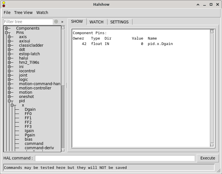
Fig. 30 Halshow tool showing the “SHOW” tab.
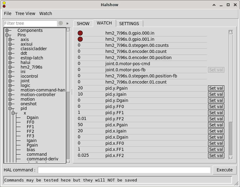
Fig. 31 Halshow tool showing the “WATCH” tab.
3.8.3.3. Halscope
halscope is a graphical tool that provides an oscilloscope for HAL. It allows capturing and displaying the values of pins, signals, and parameters over a period of time. This tool is shown in Fig. 32. The menu allows saving the current configuration or opening a previously saved configuration. When halscope is closed, the configuration is automatically saved to the autosave.halscope file.
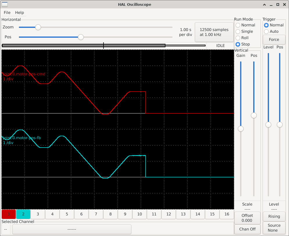
Fig. 32 Halscope tool showing the values of joint.0.motor-pos-cmd (motor position commanded by LinuxCNC) and joint.0.motor-pos-fb (motor position read from the encoder) over time.
You can open the Halscope tool from the AXIS graphical interface by clicking on .
3.8.3.4. Halreport
halreport is a command-line tool that generates a report on HAL connections. The command’s help output is as follows:
Usage:
    halreport -h | --help (this help)
or
    halreport [outfilename]
The generated report displays all signal connections and indicates potential issues. The information included in the report, among other things, is:
System description and kernel version.
Signals and their connected output, input, and input/output pins.
Functions, threads, and
addfcommands corresponding to each pin.Real names for pins that use aliases.
Signals without an output.
Signals without inputs.
Functions not added to threads.
Warnings about components marked as obsolete.
3.8.4. PyVCP (Python Virtual Control Panel)
PyVCP (Python Virtual Control Panel) is a LinuxCNC component that allows creating custom graphical user interface panels to complement the main LinuxCNC interface. These panels can be used to provide additional controls, indicators, and displays that can be tailored to specific machine requirements. The PyVCP GUI components can be connected to HAL pins for real-time interaction with the machine. Some of the PyVCP components are:
LED indicators: Visual status indicators that can show the state of a HAL pin.
Buttons: Interactive controls that can set the value of a HAL pin.
Bar displays: Graphical representations of float HAL pins.
Labels: Text displays for showing information.
Tables: Layout containers for organizing components in rows and columns.
For the complete list of components and their configuration options, consult the PyVCP section of the LinuxCNC user manual [lin23] (https://linuxcnc.org/docs/html/gui/pyvcp.html).
For our gantry robot system, we configured a PyVCP panel with LED status indicators, motor RPM displays, motor controller status indicators, and some convenient control buttons. Fig. 33 shows the LinuxCNC AXIS interface with the custom PyVCP panel integrated on the right side.
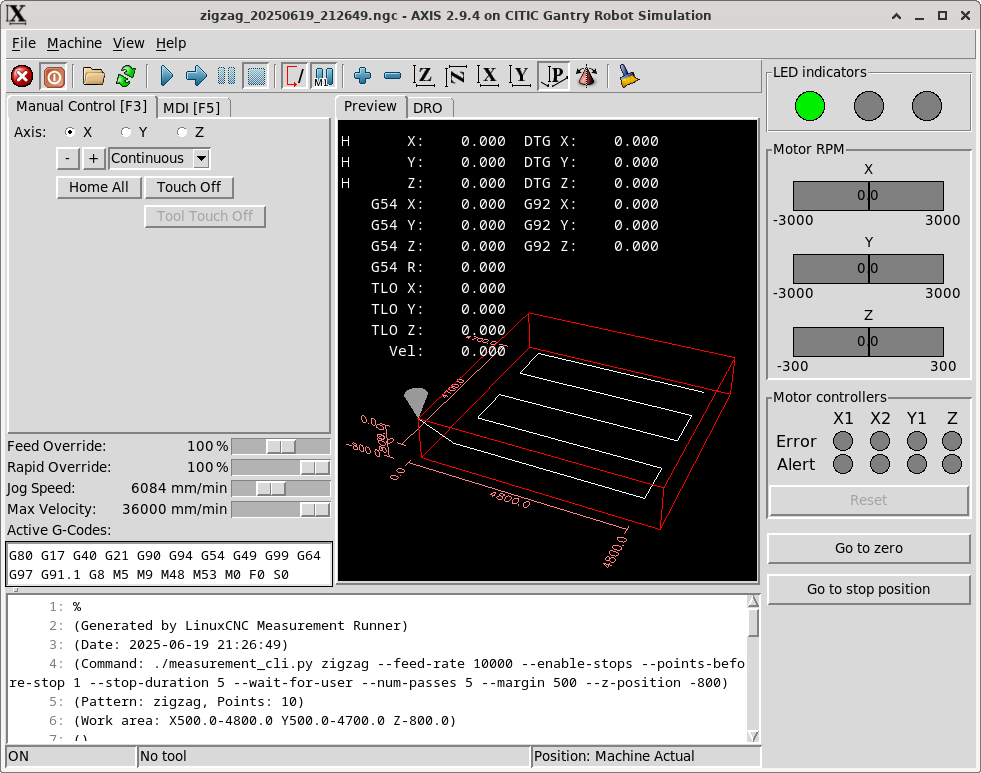
Fig. 33 LinuxCNC AXIS interface showing the custom PyVCP panel with LED indicators, motor RPM displays, controller status, and control buttons.
3.8.4.1. PyVCP Configuration
PyVCP is configured in the DISPLAY section of the INI file using the PYVCP parameter:
PYVCP = gui_panel.xml
This parameter specifies the XML file that defines the panel layout and components. The XML file must be located in the same directory as the configuration files.
By default the panel appears at the right of the AXIS user interface. The panel can be also configured to appear at the bottom of the AXIS user interface by specifying the following in the [DISPLAY] section of the INI file:
PYVCP_POSITION = BOTTOM
3.8.4.2. gui_panel.xml Configuration File
The gantry robot configuration uses a PyVCP panel that provides some monitoring and control capabilities. The panel is defined in the gui_panel.xml file and includes several functional sections. Below are the different sections of the gui_panel.xml configuration file.
LED Indicators: Displays the main system status with three colored LEDs.
 4    <labelframe text="LED indicators">
 5        <label>
 6            <!-- vertical space -->
 7            <font>("DejaVu Sans",2)</font>
 8        </label>
 9        <table flexible_rows="[1]" flexible_columns="[1,3]">
10            <tablesticky sticky="ns"/>
11            <tablerow/>
12            <led>
13                <size>30</size>
14                <on_color>"green2"</on_color>
15                <off_color>"gray50"</off_color>
16                <halpin>"led-green"</halpin>
17            </led>
18            <led>
19                <size>30</size>
20                <on_color>"yellow"</on_color>
21                <off_color>"gray50"</off_color>
22                <halpin>"led-yellow"</halpin>
23            </led>
24            <led>
25                <size>30</size>
26                <on_color>"red"</on_color>
27                <off_color>"gray50"</off_color>
28                <halpin>"led-red"</halpin>
29            </led>
30        </table>
31        <label>
32            <!-- vertical space -->
33            <font>("DejaVu Sans",2)</font>
34        </label>
35    </labelframe>
Motor RPM: Shows real-time motor RPM speeds using bar displays:
40    <labelframe text="Motor RPM">
41        <relief>SUNKEN</relief>
42        <bd>2</bd>
43        <label>
44            <text>"X"</text>
45        </label>
46        <bar>
47            <halpin>"x-rpm"</halpin>
48            <min_>-3000</min_>
49            <max_>3000</max_>
50        </bar>
51        <label>
52            <text>"Y"</text>
53        </label>
54        <bar>
55            <halpin>"y-rpm"</halpin>
56            <min_>-3000</min_>
57            <max_>3000</max_>
58        </bar>
59        <label>
60            <text>"Z"</text>
61        </label>
62        <bar>
63            <halpin>"z-rpm"</halpin>
64            <min_>-300</min_>
65            <max_>300</max_>
66        </bar>
67    </labelframe>
Motor Controllers: Displays error and alert status for each motor controller, and allows sending a reset signal to the motor controllers.
 72    <labelframe text="Motor controllers">
 73        <relief>SUNKEN</relief>
 74        <bd>2</bd>
 75        <table flexible_rows="[1,2,3]" flexible_columns="[1,2,3,4,5]">
 76            <tablesticky sticky="ns"/>
 77            <tablerow/>
 78            <label></label>
 79            <label>
 80                <text>"X1"</text>
 81                <font>("DejaVu Sans",12)</font>
 82            </label>
 83            <label>
 84                <text>"X2"</text>
 85                <font>("DejaVu Sans",12)</font>
 86            </label>
 87            <label>
 88                <text>"Y1"</text>
 89                <font>("DejaVu Sans",12)</font>
 90            </label>
 91            <label>
 92                <text>"Z"</text>
 93                <font>("DejaVu Sans",12)</font>
 94            </label>
 95
 96            <tablerow/>
 97            <label>
 98                <text>"Error"</text>
 99                <font>("DejaVu Sans",12)</font>
100            </label>
101            <led>
102                <size>20</size>
103                <on_color>"red"</on_color>
104                <off_color>"gray50"</off_color>
105                <halpin>"led-x1-error"</halpin>
106            </led>
107            <led>
108                <size>20</size>
109                <on_color>"red"</on_color>
110                <off_color>"gray50"</off_color>
111                <halpin>"led-x2-error"</halpin>
112            </led>
113            <led>
114                <size>20</size>
115                <on_color>"red"</on_color>
116                <off_color>"gray50"</off_color>
117                <halpin>"led-y-error"</halpin>
118            </led>
119            <led>
120                <size>20</size>
121                <on_color>"red"</on_color>
122                <off_color>"gray50"</off_color>
123                <halpin>"led-z-error"</halpin>
124            </led>
125
126            <tablerow/>
127            <label>
128                <text>"Alert"</text>
129                <font>("DejaVu Sans",12)</font>
130            </label>
131            <led>
132                <size>20</size>
133                <on_color>"yellow"</on_color>
134                <off_color>"gray50"</off_color>
135                <halpin>"led-x1-alert"</halpin>
136            </led>
137            <led>
138                <size>20</size>
139                <on_color>"yellow"</on_color>
140                <off_color>"gray50"</off_color>
141                <halpin>"led-x2-alert"</halpin>
142            </led>
143            <led>
144                <size>20</size>
145                <on_color>"yellow"</on_color>
146                <off_color>"gray50"</off_color>
147                <halpin>"led-y-alert"</halpin>
148            </led>
149            <led>
150                <size>20</size>
151                <on_color>"yellow"</on_color>
152                <off_color>"gray50"</off_color>
153                <halpin>"led-z-alert"</halpin>
154            </led>
155        </table>
156        <label>
157            <!-- vertical space -->
158            <font>("DejaVu Sans",2)</font>
159        </label>
160        <button>
161            <halpin>"gui-controllers-reset-button"</halpin>
162            <disable_pin>True</disable_pin>
163            <text>"Reset"</text>
164        </button>
165    </labelframe>
Control Buttons: Provides convenient buttons for common operations:
170    <button>
171        <halpin>"gui-goto-zero-position-button"</halpin>
172        <disable_pin>True</disable_pin>
173        <text>"Go to zero"</text>
174    </button>
175    <label>
176        <!-- vertical space -->
177        <font>("DejaVu Sans",2)</font>
178    </label>
179    <button>
180        <halpin>"gui-goto-stop-position-button"</halpin>
181        <disable_pin>True</disable_pin>
182        <text>"Go to stop position"</text>
183    </button>
3.8.4.3. PyVCP Integration with HAL
Each PyVCP component that needs to interact with the machine creates a corresponding HAL pin. These pins can be connected to other HAL components in a .hal configuration file to provide the desired functionality. This file has to be specified in the POSTGUI_HALFILE parameter of the HAL section of the INI file.
Examples of PyVCP components and the corresponding HAL pins are:
LED components create input pins (e.g.,
pyvcp.led-green,pyvcp.led-red)Button components create output pins (e.g.,
pyvcp.gui-goto-zero-position-button). Additionally, when thedisable_pinparameter is set totrue, adisabledpin is created (e.g.,pyvcp.gui-goto-zero-position-button.disabled).Bar displays create input pins for displaying values (e.g.,
pyvcp.x-rpm,pyvcp.y-rpm)
In our case, the corresponding PyVCP panel .hal file is gui_panel.hal.
3.8.4.4. gui_panel.hal Configuration File
The .hal file for our PyVCP panel is gui_panel.hal and is specified in the POSTGUI_HALFILE parameter of the HAL section of the INI file as shown in Section 3.8.1.2. This file is used to connect the PyVCP components to the HAL pins. The file is shown below.
 1# gui_panel.hal -- must be loaded as a postgui HAL file
 2
 3# Indicator LEDs
 4net led-red => pyvcp.led-red
 5net led-yellow => pyvcp.led-yellow
 6net led-green => pyvcp.led-green
 7
 8
 9# Motor controller LEDs
10net x1-error => pyvcp.led-x1-error
11net x2-error => pyvcp.led-x2-error
12net y-error => pyvcp.led-y-error
13net z-error => pyvcp.led-z-error
14
15net x1-alert => pyvcp.led-x1-alert
16net x2-alert => pyvcp.led-x2-alert
17net y-alert => pyvcp.led-y-alert
18net z-alert => pyvcp.led-z-alert
19
20# Motor controller reset button
21net not-fault => pyvcp.gui-controllers-reset-button.disable
22
23net gui-reset-button <= pyvcp.gui-controllers-reset-button
24net gui-reset-button => oneshot.reset.in
25
26net reset-pulse <= oneshot.reset.out
27net reset-pulse => hm2_7i96s.0.7i77.0.0.output-02
28
29
30# Go to buttons
31net gui-goto-zero-button <= pyvcp.gui-goto-zero-position-button
32net gui-goto-zero-button => halui.mdi-command-00
33net gui-goto-disable => pyvcp.gui-goto-zero-position-button.disable
34
35net gui-goto-stop-button <= pyvcp.gui-goto-stop-position-button
36net gui-goto-stop-button => halui.mdi-command-01
37net gui-goto-disable => pyvcp.gui-goto-stop-position-button.disable
38
39
40# Scale to convert from velocity in mm/s to rpm
41# - For axes X and Y:
42#   The axes move 144 mm/rev and the motors have a gearbox with a
43#   gear rate of 0.1. Hence the scale is: 60/(0.1*144) = 4.166666666666667
44# - For axis Z:
45#   The axis moves 4 mm/rev. Hence the scale is 60/4 = 15
46setp scale.x.vel-rpm.gain 4.166666666666667
47setp scale.x.vel-rpm.offset 0
48
49setp scale.y.vel-rpm.gain 4.166666666666667
50setp scale.y.vel-rpm.offset 0
51
52setp scale.z.vel-rpm.gain 15
53setp scale.z.vel-rpm.offset 0
54
55
56# Connect axis velocities with scale components
57net x1-vel-cmd => scale.x.vel-rpm.in
58net y-vel-cmd => scale.y.vel-rpm.in
59net z-vel-cmd => scale.z.vel-rpm.in
60
61
62# Connect rpm with pyvcp display
63net axis-x-motor-rpm <= scale.x.vel-rpm.out
64net axis-x-motor-rpm => pyvcp.x-rpm
65
66net axis-y-motor-rpm <= scale.y.vel-rpm.out
67net axis-y-motor-rpm => pyvcp.y-rpm
68
69net axis-z-motor-rpm <= scale.z.vel-rpm.out
70net axis-z-motor-rpm => pyvcp.z-rpm
3.8.5. Ladder Logic Programming
LinuxCNC includes the ClassicLadder component, a free implementation of a ladder interpreter published under the LGPL.
Ladder logic, or the ladder programming language, is a method for drawing electrical logic diagrams. Originally conceived to describe control systems using relays, this approach has become a widely used graphical language for programming PLC devices. It derives its name from the fact that programs in this language resemble ladders, with two vertical rails and a series of horizontal rungs between them.
To use ClassicLadder, you must load the classicladder_rt real-time module in HAL and add the classicladder.0.refresh function to the servo-thread thread using the following commands:
loadrt classicladder_rt addf classicladder.0.refresh servo-thread
Once this is done, you can open the ClassicLadder graphical interface with the system command classicladder, or from the AXIS interface by clicking on . The ClassicLadder graphical interface allows you to create ladder logic programs, as well as view the logical status of the different program components. This interface is composed of several windows, as shown in Fig. 34.
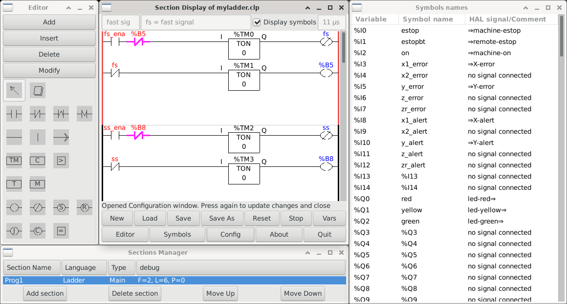
Fig. 34 ClassicLadder graphical interface.
In our gantry robot system, we use ClassicLadder to program the operation of the LED indicator panel. The program created with ClassicLadder has been saved in the myladder.clp file. To use it in LinuxCNC, we use the following commands in the citic_gantry_robot.hal file to load the classicladder_rt module and load the myladder.clp file:
57loadrt classicladder_rt
58
59addf classicladder.0.refresh servo-thread
60
61# load classic ladder project
62loadusr classicladder myladder.clp --nogui
The LinuxCNC user manual [lin23] includes a detailed guide to ClassicLadder. Another good introduction to ClassicLadder is The Feral Engineer’s “Classicladder tutorials” series on YouTube: https://www.youtube.com/playlist?list=PLTYvfbjLClpfAfJSGhZUecgXFwVPY5e09.