2.3. “Axis” Page
The “Axis” configuration page is shown in Fig. 5. As shown, the parameters use the units established on the initial configuration page (see Section 2.1); thus, position parameters are in degrees (°), speed parameters in degrees per second (°/s), and acceleration parameters in degrees per second squared (°/s^2^). The various options available on this page and their recommended settings are described below.
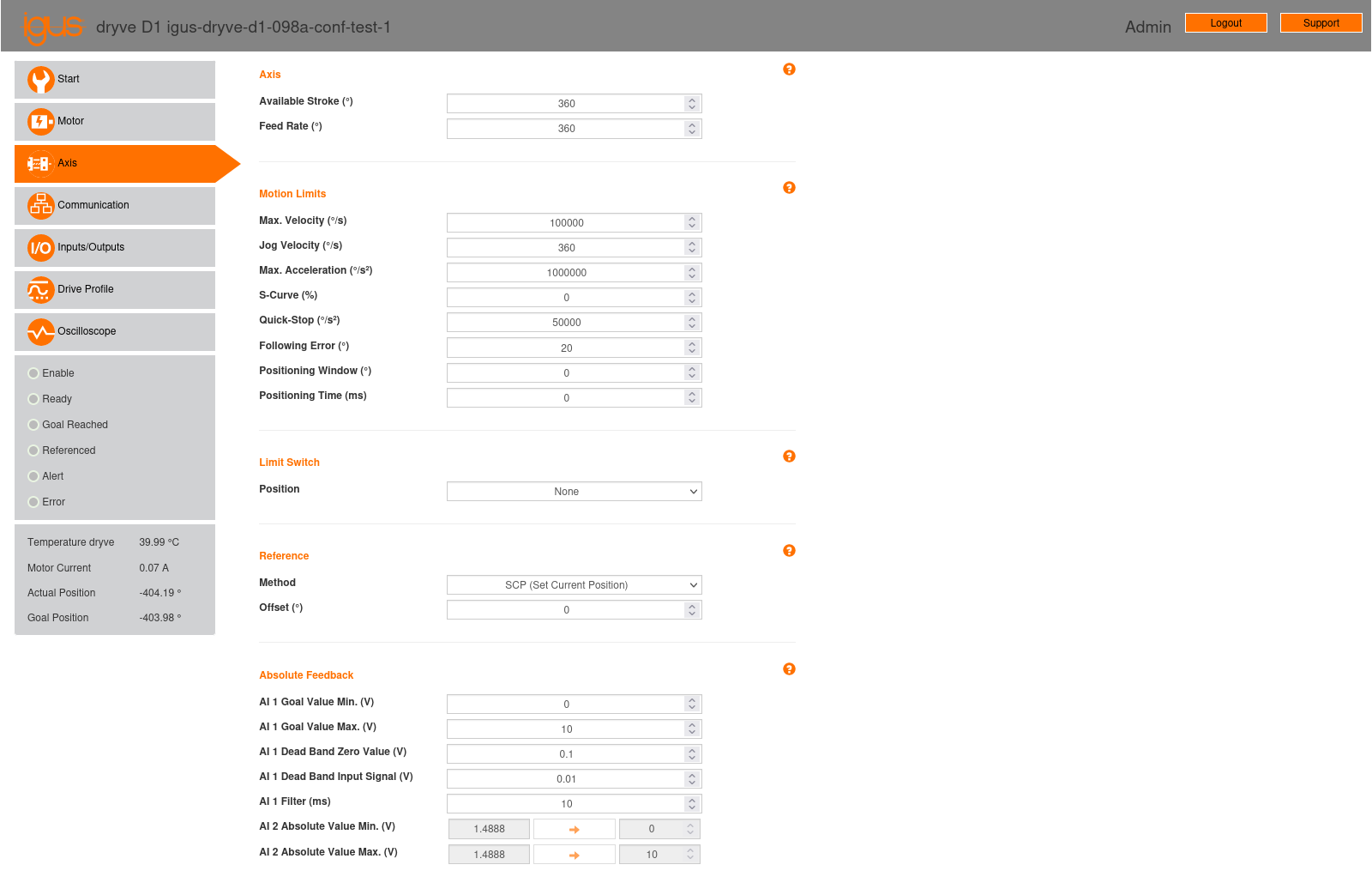
Fig. 5 “Axis” configuration page of the stepper motor controller.
2.3.1. Axis
This section contains the following parameters:
Available Stroke: Defines the movement range for the “ABS” (Absolute Positioning) mode. Since we will not be using this mode, this parameter is not relevant to our application.
Feed Rate: For linear axes, this parameter indicates the axis displacement per motor rotation. As we are considering a rotary axis, we must set this parameter to 360°, as specified in Section 5.5.1 of the controller manual.
2.3.2. Motion Limits
This section includes the following parameters:
Max. Velocity (°/s): This sets the maximum motor speed. It functions as a limit for the movement programming modes available on the “Drive Profile” page (see Section 2.6). For the stepper motor, speed will be controlled by the step signal received by the controller, so we want this parameter to be as high as possible. For the brushless motor, the maximum speed will be set on the “Drive Profile” page, with a value not exceeding that set here. Therefore, we will set this parameter to its maximum value: 100000 °/s.
Jog Velocity (°/s): This parameter defines the motor speed for manual positioning, accessible on the “Drive Profile” page (see Section 2.6). It is primarily useful for testing purposes via the controller’s web interface; in our case, we have set it to 360 °/s. For the final system, this parameter is irrelevant.
Max. Acceleration (°/s2): This sets the maximum motor acceleration, used in manual positioning on the “Drive Profile” page (see Section 2.6). It also serves as a limit in the movement programming modes available on the “Drive Profile” page. Similar to speed, for the stepper motor, acceleration will be controlled by the step signal received by the controller. For the brushless motor, the maximum acceleration will also be set on the “Drive Profile” page, with a value not exceeding that set here. Therefore, we will set this parameter to its maximum value: 1000000 °/s2.
S-Curve (%): This parameter allows control over the rate of change of acceleration, known as “jerk” [Wikipediacontributors23b]. It can be adjusted between 0% and 100% to control the smoothness of acceleration and deceleration transitions in motor movement. Lower values will result in abrupt changes in acceleration, leading to higher “jerk” levels and, consequently, less smooth movements that can induce unwanted vibrations and stress on the system. Conversely, higher values will reduce “jerk,” resulting in smoother acceleration and deceleration transitions, thereby minimizing vibrations and wear on both the motor and machinery.
If an external controller (such as LinuxCNC) is to have full control over motor movement, this parameter should be set to 0%. In this configuration, any acceleration and deceleration smoothing within the motor controller itself is deactivated, allowing the external controller to directly manage the movement.
However, LinuxCNC’s current motion controller does not have a “jerk” limitation and uses constant acceleration. It might be desirable to set this parameter to a value greater than 0% to limit “jerk” and prevent unwanted vibrations and stress on the system. However, this approach would increase tracking error within LinuxCNC. Therefore, if this option is to be set above 0%, a balance between movement smoothness and tracking precision must be found.
In our case, we have set the parameter to 0%.
Quick-Stop (°/s2): This specifies the deceleration rate when a movement stops in an emergency. A quick stop is executed if the controller’s “Enable” signal (digital input X2.7) is revoked.
Important
It is important to ensure that the specified deceleration is appropriate for the intended application. A deceleration that is too low could result in an excessive stop time for the robot’s movement; conversely, a deceleration that is too high could damage the robot’s mechanical structure.
In our testbed setup, we have set this parameter to 50000 °/s2.
Following Error (°): This defines the permissible deviation of the actual position from the desired position. A warning is issued if 50% of the allowed tracking error is reached. If the allowed tracking error is exceeded, the movement stops, and an error is reported.
In our testbed setup, we have set this parameter to 20°.
Positioning Window (°): This parameter defines a position range around a target point, extending in both positive and negative directions. For example, if the goal is to reach 100 mm and a positioning window of 10 mm is set, the system will consider the position to be within the target range if it falls anywhere between 90 mm and 110 mm. If the motor’s actual position is within this window, the movement is considered complete, even if the motor is mechanically blocked. This prevents the system from continuously attempting to reach an exact position in case of an obstruction. If the positioning window is set to 0, this function is deactivated, and the system will not consider a range around the target point.
In our testbed setup, we have set this parameter to 0, thereby deactivating this function.
Positioning Time (ms): This defines the duration, in milliseconds, for which the actual position must be maintained within the range defined by the positioning window before a movement is considered complete.
In our testbed setup, we have set this parameter to 0.
2.3.3. Limit Switch
This section includes a “Position” parameter that allows for specifying the position and number of limit sensors used.
In our testbed setup, the limit sensors are not connected to the controllers, they are only connected to the MESA 7I96S board, so limits are entirely managed by LinuxCNC. Therefore, we set the “Position” parameter to “None.”
2.3.4. Reference
This section allows for selecting the preferred referencing (“homing”) method and position displacement (“offset”).
Similar to robot movement limits (see Section 2.3.3), the “homing” process will also be fully controlled by LinuxCNC. Therefore, we have set the following parameters:
Method: SCP (Set Current Position)
Offset (°): 0
2.3.5. Absolute Feedback
The igus® dryve D1 controller has two analog inputs, AI 1 (Analog Input 1, input X4.1) and AI 2 (Analog Input 2, input X4.2). These are used to configure and control the target position or speed and the current position of the system, respectively. In our system, we will use analog input AI 1 to control the brushless motor’s speed; analog input AI 2 will not be used. For the stepper motor, these inputs are not applicable, making this section relevant only for the brushless motor. Below are the parameters related to the analog inputs available in this section.
Parameters related to AI 1 (input X4.1):
The AI 1 input will be used to control the brushless motor’s speed (see Section 2.6). The analog input control voltage will be ± 10 V, which must be configured on the “Inputs/Outputs” page (see Section 2.5). This voltage range must be considered when setting the AI 1 related parameters detailed below.
AI 1 Target Value Min. (V): The minimum voltage value at analog input AI 1. We set its value to -10 V.
AI 1 Target Value Max. (V): The maximum voltage value at analog input AI 1. We set its value to 10 V.
AI 1 Dead Band Zero Value (V): This allows for setting a dead band symmetrically around 0 V in the target signal corresponding to analog input AI 1. This parameter can be specified in increments of 0.001 V. We set its value to 0 V.
AI 1 Dead Band Input Signal (V): This allows for setting a dead band symmetrically around 0 V in the input signal of Analog Input AI 1. This parameter can be specified in increments of 0.001 V. We set its value to 0 V.
AI 1 Filter (ms): This is the interval for averaging the signal. It is used to filter sudden signal variations and prevent inconsistencies in movement. Lower values result in a system that responds quickly but is more susceptible to noise or interference. Higher values result in a more stable system but with a longer response time. We set its value to 10 ms.
The dead band parameters, “AI 1 Dead Band Zero Value” and “AI 1 Dead Band Input Signal,” can be used to minimize unwanted motor movements during the idle state caused by increased ripple in the input signal or other interferences. Considering the above parameters, if the analog input voltage \(x\) is already filtered as specified in the “AI 1 Filter” parameter, the target position or speed will be calculated using the following transfer functions:
\(f_{\text{ZV}}(\cdot)\), corresponding to the “AI 1 Dead Band Zero Value” parameter and shown in Fig. 6.
\(f_{\text{IS}}(\cdot)\), corresponding to the “AI 1 Dead Band Input Signal” parameter and shown in Fig. 7.
Thus, for the analog input value \(x\), the target position or speed will be:
\[y = (f_{\text{ZV}} \circ f_{\text{IS}})(x) = f_{\text{ZV}}(f_{\text{IS}}(x))\]Note
The calculation of the target position or speed is not explicitly stated in the controller manual (considering manual version 3.0.1) and has been determined experimentally. The manual only textually describes the “AI 1 Dead Band Zero Value” and “AI 1 Dead Band Input Signal” parameters, similar to the descriptions provided above.

Fig. 6 Transfer function \(f_{\text{ZV}}(\cdot)\).

Fig. 7 Transfer function \(f_{\text{IS}}(\cdot)\).
Parameters related to AI 2 (input X4.2):
Analog input AI 2 is used to provide position information to the controller via an analog signal. In our case, we will not be using this input, so the parameters related to it are irrelevant.
AI 2 Absolute Value Min (V): The minimum voltage value at analog input AI 2.
AI 2 Absolute Value Max (V): The maximum voltage value at analog input AI 2.