2.6. “Drive Profile” Page
This page allows you to select the control mode for executing movements. The available modes are:
Binary: Movement control using digital or analog inputs and digital outputs.
Tipp/Teach: Movement control using digital or analog inputs and digital outputs. In this mode, it is possible to modify the target positions of existing movements using digital inputs.
Step/Direction: Movement control based on step and direction signals. This mode is only available for stepper motors.
CANopen: Movement control via the CANopen communication protocol.
Modbus TCP: Movement control via the Modbus TCP communication protocol.
Next, we will describe the configurations to apply to the motors.
2.6.1. Stepper motor
For the stepper motor, we select the “step/direction” control mode. Fig. 11 shows the “Drive Profile” configuration page for the stepper motor controller when using the “step/direction” control mode. This control mode does not require any additional configuration; the page will simply show usage information for the step and direction signals.
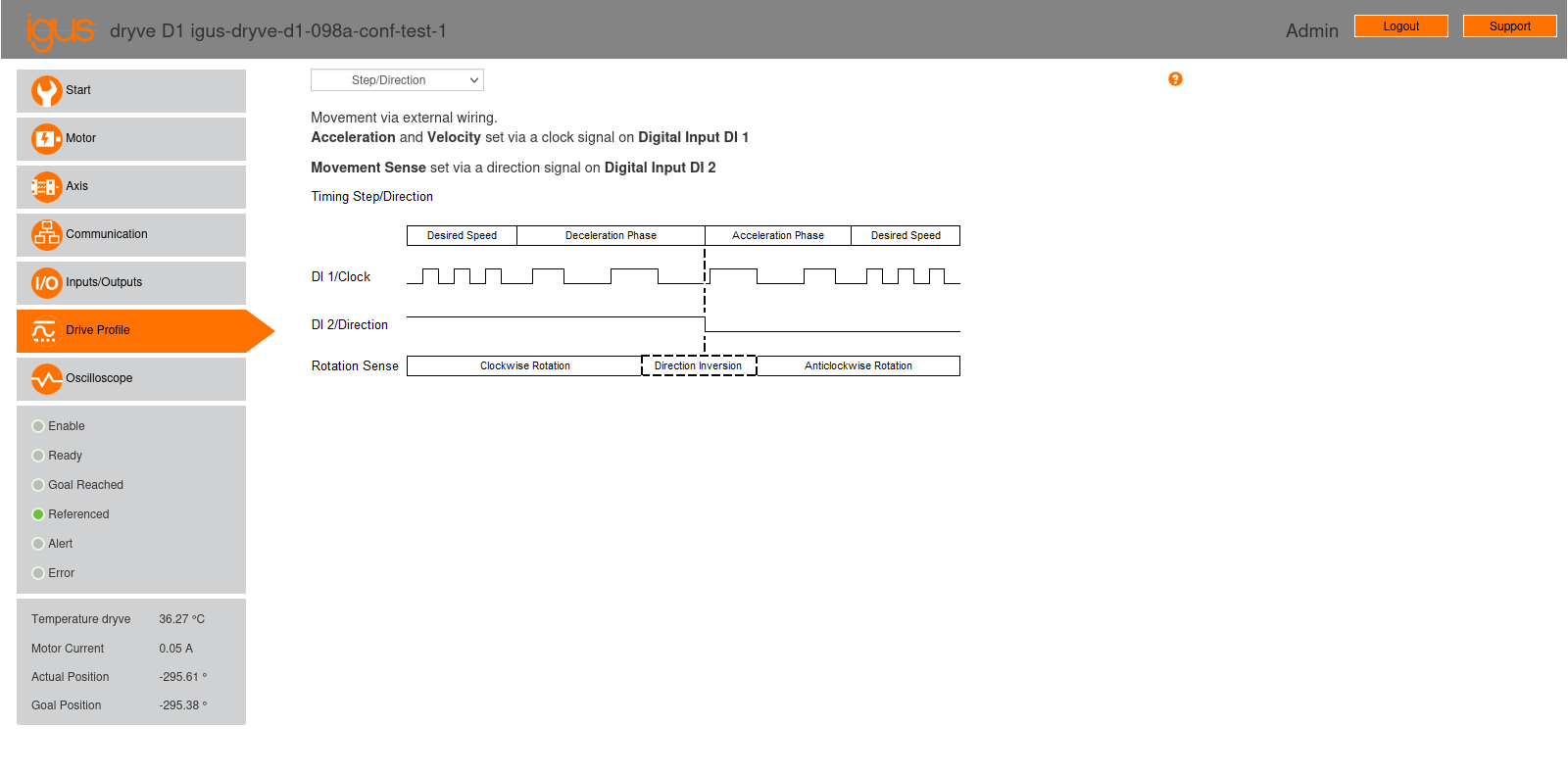
Fig. 11 “Drive Profile” configuration page of the stepper motor controller, using the “step/direction” control mode.
2.6.2. Brushless motor
For the brushless motor, we select the “binary” control mode. Fig. 12 shows the “Drive Profile” configuration page for the brushless motor controller, using the “binary” control mode. This mode provides a movement table (see Fig. 12) that allows for programming up to 32 parameterized movements, specifying the movement mode, target, maximum acceleration, speed, and the number of the next movement to execute. For the brushless motor, we will enter a single movement at position 1 using ADR (Analogue Rotation with Direction Definition) mode. ADR mode enables rotary movements by setting their speed via analog input AI 1.
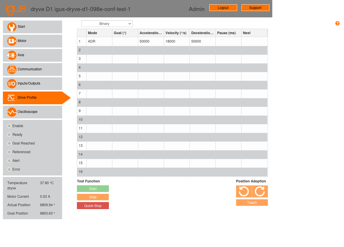
Fig. 12 “Drive Profile” configuration page of the brushless motor controller, using the “binary” control mode.
In our testbed setup, we have configured the following parameters for the movement at position 1:
Mode: ADR (Analogue Rotation with Direction Definition).
Goal (°): This field will be left empty.
Acceleration (°/s2): 50000 °/s2, which is equivalent to 138.89 rev/s2.
Velocity (°/s): 18000 °/s, which is equivalent to 3000 rpm.
Deceleration (°/s2): 50000 °/s2, identical to the acceleration setting.
Pause (ms): This field will be left empty.
Next: This field will be left empty.
As explained in Section 2.5, analog input AI 1 was configured to operate within a range of ±10 V. The controller will vary the motor speed proportionally to the applied analog signal. Thus, when input AI 1 is set to -10 V, the motor will rotate at 3000 rpm counter-clockwise, while when adjusted to 10 V, the motor will rotate at 3000 rpm clockwise.
Once the movement is configured, it must be activated for the controller to move the motor. There are two activation methods:
Select the movement by clicking on row number 1 of the movement table and then clicking the “start” button at the bottom of the page.
Use the controller’s digital inputs and outputs.
While option 1 may be suitable for testing, implementing option 2 is necessary for a production system. In this scenario, for a powered controller with the “enable” signal not yet activated, the following steps should be followed:
Set digital inputs 1 to 5 (X2.1 to X2.5) with the selected movement number minus one, where input 1 represents the least significant bit and input 5 the most significant. For example, for movement number 1, the inputs will be set to 00000; for 2, to 00001; and so on, up to 32, which will be set to 11111. For movement number 1, which is our case, digital inputs 1 to 5 can simply be left disconnected.
Set digital input 7 (X2.7, the “enable” input) to a high level.
Once the “enable” input is activated, wait for the controller to set digital output 1 (X3.1, the “ready” output) to a high level. This output indicates that the controller is prepared to accept position commands.
Once the “ready” output is activated, send a square pulse to digital input 6 (X2.6, the “start” signal) to initialize the movement program. The controller has a debounce filter with a time of 10 ms on digital inputs 1 to 10 (excluding step and direction inputs), so the pulse must have a duration greater than 10 ms for the controller to detect it. In our testbed setup, we have set the pulse duration to 100 ms.
In our testbed setup, the movement activation process has been configured in LinuxCNC and is executed using the MESA 7I77 board, which sends and receives the corresponding signals.