3.8. LinuxCNC Configuration
As noted in Section 3.6.2, a LinuxCNC configuration comprises several files, requiring at least one INI file and one HAL file. The following sections detail the configuration of both file types, using the mesa_7i96s_7i77_xy configuration as an example.
3.8.1. INI Configuration
3.8.1.1. .ini Configuration File Format
An .ini file is a plain text file used for configuring applications and programs. It has a simple structure consisting of sections and key-value pairs. The basic syntax of an .ini file is as follows:
Sections: Sections serve to organize keys and values. Each section begins with its name enclosed in square brackets, followed by zero or more key-value pairs belonging to that section. The syntax for a section is:
[section_name]Keys and Values: Within each section, keys and their corresponding values can be defined. Keys are identifiers used to access associated values. The syntax for a key-value pair is:
key = value
Keys can contain letters and underscores (
_). Values can be text strings, integers, or floating-point numbers.Comments: Comments begin with a semicolon (
;) or a hash symbol (#). For example:; This is a comment # This is also a comment
3.8.1.2. Example: mesa_7i96s_7i77_xy.ini Configuration File
Below are the different sections of the mesa_7i96s_7i77_xy.ini configuration file, with comments explaining the purpose of each parameter. Note that not all available parameters are specified in some sections. For a complete list of parameters and their documentation, consult the LinuxCNC user manual [lin23].
EMC Section: General configuration.
 1[EMC]
 2# General configuration
 3
 4# Machine name, usually displayed in the interface window.
 5MACHINE = mesa_7i96s
 6
 7# Debug flags, 0 will not print debug messages.
 8DEBUG = 0
 9
10# Configuration version, for LinuxCNC 2.9 it should be 1.1.
11VERSION = 1.1
DISPLAY Section: User interface configuration. The available options may depend on the specific user interface used. In this case, we are using the AXIS user interface.
14[DISPLAY]
15# Graphic interface configuration
16
17# Type of graphic interface to use.
18DISPLAY = axis
19
20# Coordinate system: RELATIVE or MACHINE.
21POSITION_OFFSET = MACHINE
22
23# Coordinates to display: COMMANDED or ACTUAL.
24POSITION_FEEDBACK = ACTUAL
25
26# Maximum "feed override". A "feed override" of 2 means
27# 200% of the programmed "feed rate".
28MAX_FEED_OVERRIDE = 2.000000
29
30# Image to display on the splash screen.
31INTRO_GRAPHIC = linuxcnc.gif
32
33# Maximum time in seconds for the splash screen.
34INTRO_TIME = 5
35
36# Default directory for G-code programs.
37PROGRAM_PREFIX = /home/gtec/linuxcnc/nc_files
38
39# Increments to move the robot with manual control.
40INCREMENTS = 5mm 1mm .5mm .1mm .05mm .01mm .005mm
41
42# The coordinate value to be displayed: COMMANDED or ACTUAL
43POSITION_FEEDBACK = ACTUAL
44
45# Default linear velocity with manual control.
46DEFAULT_LINEAR_VELOCITY = 1.000000
47
48# Maximum allowed linear velocity with manual control.
49MAX_LINEAR_VELOCITY = 10.000000
50
51# Minimum allowed linear velocity with manual control.
52MIN_LINEAR_VELOCITY = 0.000000
53
54# Text editor to use when clicking File -> Edit.
55EDITOR = mousepad
56
57# Geometry of the 3D view in the preview window.
58GEOMETRY = XY
59
60# Refresh time in milliseconds.
61CYCLE_TIME = 100
62
63# File to open when starting LinuxCNC (optional).
64OPEN_FILE = ""
TASK Section: LinuxCNC task controller configuration. The task controller is responsible for communicating with the user interface, the motion planner, and the G-code interpreter. Currently,
milltaskis the only task controller available. For more information, consult the LinuxCNC user manual [lin23] and themilltaskman page, also available at http://linuxcnc.org/docs/devel/html/man/man1/milltask.1.html.67[TASK] 68# Task controller configuration 69 70# Task controller module, milltask. 71TASK = milltask 72 73# Execution period of milltask. 74CYCLE_TIME = 0.010
RS274NGC Section: RS274NGC (G-code) interpreter configuration.
77[RS274NGC]
78# RS274NGC interpreter configuration
79
80# Interpreter variable file.
81PARAMETER_FILE = linuxcnc.var
82
83# Startup codes for the interpreter.
84RS274NGC_STARTUP_CODE = G21 G40 G90 G94 G97 G64 P0.025
EMCMOT Section: Motion controller configuration. The
EMCMOTandSERVO_PERIODparameters are not directly used by LinuxCNC but are used to configure the motion control module in the HAL file (see Section 3.8.2).87[EMCMOT] 88# Motion controller configuration 89 90# Motion controller module, motmod. 91# Not used by LinuxCNC directly, used in the HAL file. 92EMCMOT = motmod 93 94# Number of seconds to wait for the motion module to 95# confirm receipt of messages from the task module. 96COMM_TIMEOUT = 1.0 97 98# "servo" thread period 99# Not used by LinuxCNC directly, used in the HAL file. 100SERVO_PERIOD = 1000000
HAL Section: HAL configuration.
103[HAL]
104# Hardware Abstraction Layer (HAL) configuration
105
106# Add the HAL user interface pins.
107HALUI = halui
108
109# HAL file to execute when starting LinuxCNC.
110# Can be specified multiple times.
111HALFILE = mesa_7i96s_7i77_xy.hal
112
113# HAL file to execute after loading the graphical interface.
114POSTGUI_HALFILE = postgui.hal
115
116# HAL file to execute when closing LinuxCNC.
117SHUTDOWN = shutdown.hal
HALUI Section: HALUI (HAL-based user interface) configuration. The only available option is
MDI_COMMAND, which allows MDI commands to be executed via HAL signals. In our case, this section is left empty.120[HALUI] 121# HAL User Interface 122 123# MDI Command. Can be specified multiple times. 124# To execute it use the halui.mdi-command-NN pin, 125# where NN is the command number. 126# MDI_COMMAND = G1 X0 Y0 Z0
KINS Section: Kinematics configuration.
129[KINS]
130# Kinematics
131
132# Number of joints (motors).
133JOINTS = 2
134
135# Kinematics module
136# Not used by LinuxCNC directly, used in the HAL file.
137KINEMATICS = trivkins coordinates=XY
APPLICATIONS Section: LinuxCNC allows applications to be launched at startup. These applications must be specified within the
APPLICATIONSsection using theAPPoption, which can be used multiple times. Applications will be launched either at the beginning, before the graphical interface starts, or after a delay specified by theDELAYoption.140[APPLICATIONS] 141# Additional applications 142 143# Application to execute. Can be specified multiple times. 144APP=halscope 50000
TRAJ Section: Trajectory planner configuration.
147[TRAJ]
148# Trajectory planner configuration
149
150# Controlled axes. Possible values: X, Y, Z, A, B, C, U, V, W.
151# An axis can be specified more than once, e.g., XXYZ.
152COORDINATES =  XY
153
154# Units for linear axes.
155LINEAR_UNITS = mm
156
157# Units for rotary axes.
158ANGULAR_UNITS = degree
159
160# Maximum linear velocity, in units per second.
161MAX_LINEAR_VELOCITY = 12.00
162
163# Maximum linear acceleration, in units per second^2.
164MAX_LINEAR_ACCELERATION = 20.0
EMCIO Section: Input/output controller configuration. This controls input/output tasks such as coolant, tool changes, and emergency stops.
167[EMCIO]
168# Input/Output (I/O) controller configuration
169
170# Input/output controller module.
171EMCIO = io
172
173# Period at which EMCIO will be executed.
174CYCLE_TIME = 0.100
AXIS_<i> Section: Configuration for axis <i>. Possible values for <i> include
X,Y,Z,A,B,C,U,V, andW. An example of the X-axis configuration is provided below; the Y-axis configuration is similar.Important
When configuring the robot’s limits (
MIN_LIMITandMAX_LIMITparameters), it is advisable to leave some margin beyond the desired workspace. If the robot is commanded to position itself at one of the limits, it can easily exceed that limit slightly. For example, if you want your robot to operate on the X-axis between X = 0 and X = 200, you could configureMIN_LIMIT = -5andMAX_LIMIT = 205.177[AXIS_X] 178# X axis configuration 179 180# Maximum axis velocity, in units per second. 181MAX_VELOCITY = 12.0 182 183# Maximum axis acceleration, in units per second^2. 184MAX_ACCELERATION = 20.0 185 186# Minimum limit for the axis, in machine units. 187MIN_LIMIT = -5 188 189# Maximum limit for the axis, in machine units. 190MAX_LIMIT = 205.0
JOINT_<n> Section: Configuration for joint (motor) <n>, where <n> is the joint number, ranging from 0 to (<num_joints> \(-\) 1). The value of <num_joints> is set in the
JOINTSoption of theKINSsection.For machines with Cartesian geometries, such as gantry robots, LinuxCNC includes the
trivkinskinematics module. With this module, by default, there is a 1:1 correspondence between the axis coordinate letter and the joint number, i.e., JOINT_0 = X, JOINT_1 = Y, …, JOINT_8 = W.The
trivkinsmodule accepts thecoordinatesparameter to specify the association of axis coordinate letters with the joint number. For example, with the parametercoordinates=XZ, JOINT_0 will be assigned to X and JOINT_1 to Z. In this parameter, the same axis letter can be specified multiple times, allowing multiple joints to be assigned to the same axis. In this case, it is also necessary to use thekinstype=Bparameter. For instance, with the parameterscoordinates=XXandkinstype=B, both JOINT_0 and JOINT_1 will be assigned to X.For more information about the
trivkinskinematics module, consult thekinsman page, also available at http://linuxcnc.org/docs/devel/html/man/man9/kins.9.html.Important
Both the joint and axis configurations include
MAX_VELOCITY,MAX_ACCELERATION,MIN_LIMIT, andMAX_LIMITparameters. When the robot is not homed, LinuxCNC uses the parameters from the joint sections; however, once the robot is homed, it uses the parameters from the axis sections.The following code shows the configuration of joint 1 (X-axis), which corresponds to the stepper motor. The parameters specified below the comment “Custom configurations for the HAL file” are not directly used by LinuxCNC; they are used to configure the motor parameters in the HAL file (see Section 3.8.2).
193[JOINT_0]
194# Configuration of the first linear motor (X axis)
195
196# Motor type, LINEAR or ANGULAR.
197TYPE = LINEAR
198
199# Maximum tracking error, in machine units.
200FERROR = 1.0
201
202# Maximum tracking error at slow speeds.
203MIN_FERROR = 0.2
204
205# Maximum motor velocity, in units per second.
206MAX_VELOCITY = 12.0
207
208# Maximum motor acceleration, in units per second^2.
209MAX_ACCELERATION = 20.0
210
211# Minimum motor limit, in machine units.
212MIN_LIMIT = -5
213
214# Maximum motor limit, in machine units.
215MAX_LIMIT = 205.0
216
217# Position to which the joint will move upon completion of
218# the homing process.
219HOME = 0
220
221# Used to define the homing order.
222HOME_SEQUENCE = 0
223
224# Home switch position, in machine units.
225HOME_OFFSET = -10
226
227# Initial homing search velocity, in units per second.
228HOME_SEARCH_VEL = -1
229
230# Final homing search velocity, in units per second.
231HOME_LATCH_VEL = -0.25
232
233# Final homing velocity, in units per second.
234HOME_FINAL_VEL = 2
235
236# Ignore limit switches during homing.
237# = YES if the same switch is used for limits and homing.
238HOME_IGNORE_LIMITS = YES
239
240# The switch is shared with another joint.
241HOME_IS_SHARED = 0
242
243# Use the encoder's index pulse for homing.
244HOME_USE_INDEX = NO
245
246# ---------------------------------------------------
247# Custom configurations for the HAL file.
248# ---------------------------------------------------
249
250# *** Step generation configuration ***
251
252# Minimum duration of the stable direction signal before
253# starting a step, in nanoseconds.
254DIRSETUP = 10000
255
256# Minimum duration of the direction signal after finishing
257# a step, in nanoseconds.
258DIRHOLD = 10000
259
260# Duration of the step signal, in nanoseconds.
261STEPLEN = 2500
262
263# Minimum interval between step signals, in nanoseconds.
264STEPSPACE = 2500
265
266# Step scale. position = steps / STEP_SCALE.
267# To move the axis 1mm/rev with a 1.8° step motor and 1/32
268# step mode, STEP_SCALE = steps / position = (32*360/1.8)/1 = 6400
269STEP_SCALE = 6400
270
271# Maximum velocity, in position units per second.
272STEPGEN_MAXVEL = 17
273
274# Maximum acceleration, in position units per second^2.
275STEPGEN_MAXACCEL = 62.5
276
277# Note: It is recommended that STEPGEN_MAXVEL and STEPGEN_MAXACCEL be
278# between 1% and 25% larger than MAX_VELOCITY and MAX_ACCELERATION.
279
280
281# *** Encoder configuration ***
282
283# Encoder scale. position = counts / ENCODER_SCALE.
284# To get 1mm/rev with a 1000 ppr encoder (4000 cpr),
285# ENCODER_SCALE = counts / position = 4000 / 1 = 4000
286ENCODER_SCALE = 4000.0
287
288
289# *** PID controller configuration ***
290
291P = 50.0
292I = 20.0
293D = 0.0
294FF0 = 0.0
295FF1 = 1.0
296FF2 = 0.025
297BIAS = 0.0
298DEADBAND = 0.0
299MAX_OUTPUT = 0.0
The following code shows the configuration of joint 2 (Y-axis), which corresponds to the brushless motor. As before, the parameters specified below the comment “Custom configurations for the HAL file” are not directly used by LinuxCNC; they are used to configure the motor parameters in the HAL file (see Section 3.8.2). These parameters differ from the previous ones because now a brushless motor is used.
318[JOINT_1]
319# Configuration of the second linear motor (Y axis)
320
321# Motor type, LINEAR or ANGULAR.
322TYPE = LINEAR
323
324# Maximum tracking error, in machine units.
325FERROR = 1
326
327# Maximum tracking error at slow speeds.
328MIN_FERROR = 0.2
329
330# Maximum motor velocity, in units per second.
331MAX_VELOCITY = 12.0
332
333# Maximum motor acceleration, in units per second^2.
334MAX_ACCELERATION = 20.0
335
336# Minimum motor limit, in machine units.
337MIN_LIMIT = -5
338
339# Maximum motor limit, in machine units.
340MAX_LIMIT = 205.0
341
342# Position to which the joint will move upon completion of
343# the homing process.
344HOME = 0
345
346# Used to define the homing order.
347HOME_SEQUENCE = 1
348
349# Home switch position, in machine units.
350HOME_OFFSET = -10
351
352# Initial homing search velocity, in units per second.
353HOME_SEARCH_VEL = -1
354
355# Final homing search velocity, in units per second.
356HOME_LATCH_VEL = -0.25
357
358# Final homing velocity, in units per second.
359HOME_FINAL_VEL = 2
360
361# Ignore limit switches during homing.
362# = YES if the same switch is used for limits and homing.
363HOME_IGNORE_LIMITS = YES
364
365# The switch is shared with another joint.
366HOME_IS_SHARED = 0
367
368# Use the encoder's index pulse for homing.
369HOME_USE_INDEX = NO
370
371# ---------------------------------------------------
372# Custom configurations for the HAL file.
373# ---------------------------------------------------
374
375# *** Analog output configuration for +-10V ***
376
377# Maximum velocity in units per second.
378ANALOGOUT_MAXLIM = 50
379
380# Minimum velocity in units per second.
381ANALOGOUT_MINLIM = -50
382
383# Analog output scale. Vout = 10 * velocity / ANALOGOUT_SCALE.
384# Maximum velocity in units per second that the motor can reach.
385# For a max velocity of X rpm, with Y ppr encoder (4*Y cpr),
386# ANALOGOUT_SCALE = X / 60 * ENCODER_SCALE / (4*Y).
387# For 3000 rpm, ANALOGOUT_SCALE = 3000 / 60 * 2048 / 2048 = 50
388ANALOGOUT_SCALE = 50
389
390
391# *** Encoder configuration ***
392
393# Encoder scale. position = counts / ENCODER_SCALE.
394# To get 1mm/rev with a 512 ppr encoder (2048 cpr),
395# ENCODER_SCALE = counts / position = 2048 / 1 = 2048
396ENCODER_SCALE = 2048.0
397
398
399# *** PID controller configuration ***
400
401P = 20.0
402I = 10.0
403D = 0.0
404FF0 = 0.0
405FF1 = 1.0
406FF2 = 0.01
407BIAS = 0.0
408DEADBAND = 0.0
409MAX_OUTPUT = 0.0
3.8.2. HAL Configuration
HAL is a fundamental component of LinuxCNC, serving as an interface between the machine’s software and hardware. It provides the infrastructure for communication among the system’s numerous software and hardware components. The HAL layer is composed of components that:
Are interconnected, processing incoming data and providing outputs to other components (e.g., the motion planning algorithm instructs the motors on their movement).
Possess the ability to communicate with hardware.
Always run periodically in one of the following ways:
As real-time components, either with an execution frequency of a few microseconds (e.g., to advance a stepper motor or read an encoder) or with a frequency less than one millisecond (e.g., to adjust the planning of subsequent movements to complete a G-code instruction).
As non-real-time user-space components, which can be interrupted or delayed if the rest of the system is busy or overloaded.
The HAL components included with LinuxCNC are listed in the user manual [lin23], also available at http://linuxcnc.org/docs/stable/html/hal/components.html. Additionally, each component has its own man page.
3.8.2.1. Basic Concepts
Pins and Signals: HAL is based on the same principles used to design electrical circuits and hardware systems, employing “pins” and “signals” to represent the flow of data between HAL modules or components. In summary:
Pins can carry boolean, float, and signed or unsigned integer values.
Pins have a direction: input (IN), output (OUT), or input/output (I/O).
A signal identifies a connection between pins.
Fig. 26 from the LinuxCNC documentation [lin23] illustrates the concepts of components, pins, and signals in HAL. In the figure, pin
pin3-outofcomponent.0connects to pinspin3-inandpin4-inofcomponent.1(via thesignal-redsignal), and pinpin1-outofcomponent.1connects to pinpin1-inofcomponent.0(via thesignal bluesignal).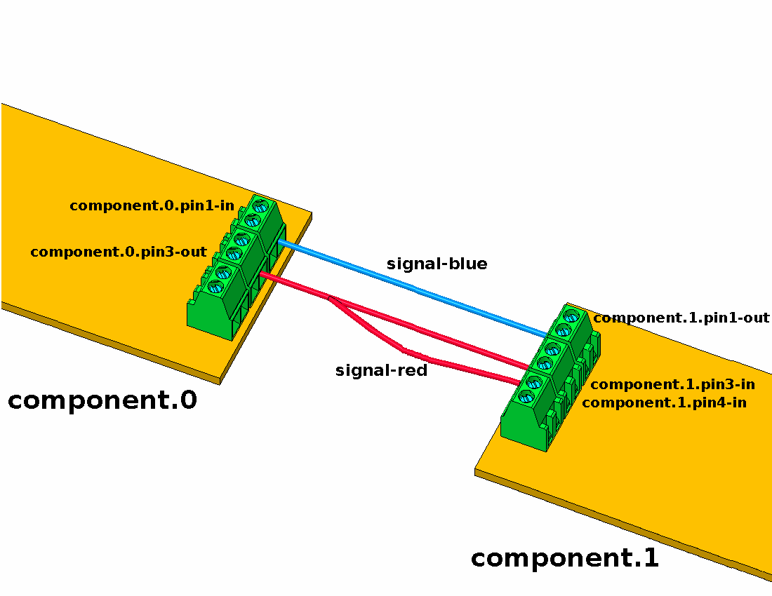
Fig. 26 HAL Concept — Connection as electrical circuits. Source: LinuxCNC documentation [lin23].
Parameters: HAL components can have parameters, which are input or output settings not connected to any other component. There are two types of parameters:
Input parameters: Values that the user can adjust and that remain fixed once configured.
Output parameters: Values that cannot be adjusted by the user. They allow for internal signals to be monitored.
Functions: Each HAL component has one or more functions that must be executed to perform the component’s task. For these functions to be executed, they must be added to a thread.
Threads: Threads enable HAL component functions to be executed at specific time intervals. When a thread is created, the time interval at which its assigned functions will be executed is specified. Subsequently, the functions of the HAL components can be added to the thread to be executed in order at the thread’s defined time interval.
3.8.2.2. Interaction with HAL and Commands
HAL does not interact directly with the user. LinuxCNC provides various interfaces to configure or interact with HAL:
From
.halfiles.From the command line using the
halcmdcommand.From Python scripts.
From C/C++ programs.
Configuration or interaction with HAL using any of these interfaces is performed through commands. The complete list of commands is detailed in the halcmd man page, also available at http://linuxcnc.org/docs/html/man/man1/halcmd.1.html. The most relevant commands are:
Note
Generally, each command must be specified on a single line. If a command needs to be split across multiple lines, a backslash (\) character can be used to indicate that the line continues to the next. The backslash must be the last character before the new line.
loadrt: Loads a HAL real-time component into the system. The basic syntax of theloadrtcommand is:loadrt <component> <options>
where
<component>is the name of the component and<options>are the component options. For example:loadrt mux4 count=1
addf: Adds a function to a real-time thread. The syntax of theaddfcommand is:addf <function> <thread>
where
<function>is the name of the function and<thread>is the thread to which it will be added. For example:addf mux4.0 servo-thread
loadusr: Loads a non-real-time HAL component into the system. Non-real-time components are separate processes that can optionally communicate with other HAL components via pins and parameters. Real-time components cannot be loaded into non-real-time space. The syntax of theloadusrcommand is:loadusr [<flags>] <command>
where
<command>is the program command to be executed and<flags>can be one or more of the following options:-i: Ignore the program’s return value (with-w).-w: Wait for the program to finish.-W: Wait for the component to be ready. It is assumed that the component will have the same name as the first argument of the command.-Wn``<name>: Wait for the component to be ready and assign it the name<name>. This is only applicable if the component has the-noption to assign a name.For example:
loadusr -Wn spindle gs2_vfd -n spindle
net: Creates a connection between a signal and one or more pins. The syntax is as follows:net <signal> <pin>
where
<signal>is the name of the signal and<pin>is the name of a pin. If the signal does not exist, a new signal is created. The command also allows the use of the words<=,=>, and<=>, separated by a space from the pin names, to indicate the direction of the signals between pins. These words are ignored by the command and merely serve to facilitate readability.The following rules must be met to connect a pin to a signal:
An input (IN) pin can always be connected to a signal.
An input/output (I/O) pin can be connected unless there is an output (OUT) pin on the signal.
An output (OUT) pin can be connected only if there are no other output (OUT) or input/output (I/O) pins on the signal.
The same signal name can be used in multiple
netcommands to connect additional pins, provided the above rules are respected.Examples:
net home-x joint.0.home-sw-in <= parport.0.pin-11-in
where
home-xis the signal name,joint.0.home-sw-inis an input (IN) pin,<=is the optional direction arrow (ignored by the command), andparport.0.pin-11-inis an output (OUT) pin.This example can also be equivalently defined in HAL by two
netcommands:net home-x <= parport.0.pin-11-in net home-x => joint-0.home-sw-in
Note
As seen in this example, although the second pin’s name has the
-insuffix, HAL treats it as an output pin. Therefore, when configuring pin connections in HAL, always refer to how the pin is configured in HAL, not just its name.net xStep stepgen.0.out => parport.0.pin-02-out parport.0.pin-08-out
where
xStepis the signal name,stepgen.0.outis an output pin, andparport.0.pin-02-outandparport.0.pin-08-outare input pins.This example can also be defined in HAL by two
netcommands as follows:net home-x <= stepgen.0.out net home-x => parport.0.pin-02-out parport.0.pin-08-out
setp: Sets the value of a pin or parameter. Valid values depend on the pin or parameter’s data type. The syntax of this command is:setp <name> <value>
where
<name>is the name of the pin or parameter and<value>is the value to which it is to be set. The command will fail if<name>does not exist as a pin or parameter, if it is a read-only parameter, if it is an output (OUT) pin, if it is a pin that is already connected to a signal, or if<value>is not a valid value for the pin or parameter’s data type.sets: Sets the value of a signal. The syntax is:sets <signal> <value>
where
<signal>is the name of the signal and<value>is the value to which it is to be set. The command will fail if<signal>does not exist as a signal, if the signal is already connected to an output (OUT) pin, or if<value>is not a valid value for the signal’s data type.unlinkp: Unlinks a pin from its connected signal. The syntax of the command is:unlinkp <name>
where
<name>is the name of the pin. If the pin does not have a connected signal, nothing happens. The command will fail if<name>does not exist as a pin.
3.8.2.3. .hal File Format
A .hal file is a plain text file containing HAL commands. Comments can be included by starting lines with the hash symbol (#). Options from the .ini file can be accessed with the syntax [<section>]<option>, where [<section>] is the section name in square brackets and <option> is the corresponding option name within that section.
3.8.2.4. Example: mesa_7i96s_7i77_xy.hal Configuration File
As noted in Section 3.6.2, a LinuxCNC configuration includes at least one .ini file and one .hal file. Below is the mesa_7i96s_7i77_xy.hal configuration file, corresponding to the mesa_7i96s_7i77_xy.ini file detailed in Section 3.8.1. Unlike the .ini format, the .hal format does not have a formal section syntax; however, for clarity, the file is presented below divided into different parts.
Load modules, add functions to threads, and other initial configurations:
 1# Load kinematics module
 2loadrt [KINS]KINEMATICS
 3
 4# Load motion controller module
 5# The "servo_period_nsec" option creates the "servo-thread" thread
 6loadrt [EMCMOT]EMCMOT servo_period_nsec=[EMCMOT]SERVO_PERIOD num_joints=[KINS]JOINTS
 7
 8# Load MESA board controller
 9loadrt hostmot2
10
11# Load MESA low-level Ethernet Anything IO boards controller
12# (Mesa Electronics Ethernet Anything IO boards)
13loadrt hm2_eth board_ip="10.68.33.122" config="num_encoders=2 num_pwmgens=0 num_stepgens=1"
14
15# Load ladder language module
16loadrt classicladder_rt
17
18# Load pid module and create a controller for each axis
19loadrt pid names=pid.x,pid.y
20
21# Load estop_latch module to handle emergency stop
22loadrt estop_latch
23
24# Load oneshot module (pulse generator)
25loadrt oneshot
26
27# Load logic module and define a 5-input OR function
28loadrt logic names=logic.fault personality=0x205
29
30# Configure the watchdog timeout for the MESA 7I96S board
31setp hm2_7i96s.0.watchdog.timeout_ns 5000000
32
33# Configure dpll (digital phase locked loop) of the hostmot2 module
34setp hm2_7i96s.0.dpll.01.timer-us -100
35setp hm2_7i96s.0.stepgen.timer-number 1
36setp hm2_7i96s.0.encoder.timer-number 1
37
38# Configure pulse parameters of the oneshot module
39setp oneshot.0.width 0.1
40
41# Add functions to the servo thread
42addf motion-command-handler servo-thread
43addf motion-controller servo-thread
44addf pid.x.do-pid-calcs servo-thread
45addf pid.y.do-pid-calcs servo-thread
46addf hm2_7i96s.0.read servo-thread
47addf hm2_7i96s.0.write servo-thread
48addf classicladder.0.refresh servo-thread
49addf estop-latch.0 servo-thread
50addf oneshot.0 servo-thread
51addf logic.fault servo-thread
52
53# Load classicladder project
54loadusr classicladder myladder.clp --nogui
X-axis configuration (joint 0, stepper motor):
 57#********************
 58# AXIS X --- JOINT 0
 59#********************
 60
 61# --- PID controller parameters ---
 62
 63setp pid.x.Pgain     [JOINT_0]P
 64setp pid.x.Igain     [JOINT_0]I
 65setp pid.x.Dgain     [JOINT_0]D
 66setp pid.x.bias      [JOINT_0]BIAS
 67setp pid.x.FF0       [JOINT_0]FF0
 68setp pid.x.FF1       [JOINT_0]FF1
 69setp pid.x.FF2       [JOINT_0]FF2
 70setp pid.x.deadband  [JOINT_0]DEADBAND
 71setp pid.x.maxoutput [JOINT_0]MAX_OUTPUT
 72setp pid.x.error-previous-target true
 73setp pid.x.maxerror 1
 74
 75
 76# --- Pulse generator parameters ---
 77
 78setp hm2_7i96s.0.stepgen.00.control-type   1  # Velocity control
 79setp hm2_7i96s.0.stepgen.00.step_type      0  # Step/dir
 80setp hm2_7i96s.0.stepgen.00.dirsetup       [JOINT_0]DIRSETUP
 81setp hm2_7i96s.0.stepgen.00.dirhold        [JOINT_0]DIRHOLD
 82setp hm2_7i96s.0.stepgen.00.steplen        [JOINT_0]STEPLEN
 83setp hm2_7i96s.0.stepgen.00.stepspace      [JOINT_0]STEPSPACE
 84setp hm2_7i96s.0.stepgen.00.position-scale [JOINT_0]STEP_SCALE
 85setp hm2_7i96s.0.stepgen.00.maxaccel       [JOINT_0]STEPGEN_MAXACCEL
 86setp hm2_7i96s.0.stepgen.00.maxvel         [JOINT_0]STEPGEN_MAXVEL
 87
 88
 89# --- Encoder parameters ---
 90
 91setp hm2_7i96s.0.encoder.00.counter-mode 0
 92setp hm2_7i96s.0.encoder.00.filter 1
 93setp hm2_7i96s.0.encoder.00.scale [JOINT_0]ENCODER_SCALE
 94
 95
 96# --- Connect pid / stepgen / motion signals ---
 97
 98net pid-x-index-enable => pid.x.index-enable
 99
100net pid-x-output <= pid.x.output
101net pid-x-output => hm2_7i96s.0.stepgen.00.velocity-cmd
102
103net pid-x-enable <= joint.0.amp-enable-out
104net pid-x-enable => pid.x.enable
105net pid-x-enable => hm2_7i96s.0.stepgen.00.enable
106
107net pid-x-pos-cmd <= joint.0.motor-pos-cmd
108net pid-x-pos-cmd => pid.x.command
109
110# net pid-x-pos-fb <= hm2_7i96s.0.stepgen.00.position-fb
111net pid-x-pos-fb <= hm2_7i96s.0.encoder.00.position
112net pid-x-pos-fb => pid.x.feedback
113net pid-x-pos-fb => joint.0.motor-pos-fb
114
115
116# --- Configure home / limit signals ---
117
118net x-sw <= hm2_7i96s.0.gpio.000.in
119net x-sw => joint.0.home-sw-in
120net x-sw => joint.0.neg-lim-sw-in
Y-axis configuration (joint 1, brushless motor):
123# MDI Command. Can be specified multiple times.
124# To execute it use the halui.mdi-command-NN pin,
125# where NN is the command number.
126# MDI_COMMAND = G1 X0 Y0 Z0
127
128
129[KINS]
130# Kinematics
131
132# Number of joints (motors).
133JOINTS = 2
134
135# Kinematics module
136# Not used by LinuxCNC directly, used in the HAL file.
137KINEMATICS = trivkins coordinates=XY
138
139
140[APPLICATIONS]
141# Additional applications
142
143# Application to execute. Can be specified multiple times.
144APP=halscope 50000
145
146
147[TRAJ]
148# Trajectory planner configuration
149
150# Controlled axes. Possible values: X, Y, Z, A, B, C, U, V, W.
151# An axis can be specified more than once, e.g., XXYZ.
152COORDINATES =  XY
153
154# Units for linear axes.
155LINEAR_UNITS = mm
156
157# Units for rotary axes.
158ANGULAR_UNITS = degree
159
160# Maximum linear velocity, in units per second.
161MAX_LINEAR_VELOCITY = 12.00
162
163# Maximum linear acceleration, in units per second^2.
164MAX_LINEAR_ACCELERATION = 20.0
165
166
167[EMCIO]
168# Input/Output (I/O) controller configuration
169
170# Input/output controller module.
171EMCIO = io
172
173# Period at which EMCIO will be executed.
174CYCLE_TIME = 0.100
175
176
177[AXIS_X]
178# X axis configuration
Other configurations:
182#***************
183# Other signals
184#***************
185
186# --- Igus controller alert and error signals ---
187
188net X-alert <= hm2_7i96s.0.7i77.0.0.input-08
189net X-error <= hm2_7i96s.0.7i77.0.0.input-09
190
191net Y-alert <= hm2_7i96s.0.7i77.0.0.input-01
192net Y-error <= hm2_7i96s.0.7i77.0.0.input-02
193
194
195# --- External emergency stop ---
196
197net remote-estop <= hm2_7i96s.0.7i77.0.0.input-13
198
199
200# --- Fault signal (logic.fault) ---
201# The fault signal will be activated if an Igus controller
202# emits an error or alert signal or the user presses the
203# emergency stop button (ESTOP).
204
205net X-alert => logic.fault.in-00
206net X-error => logic.fault.in-01
207
208net Y-alert => logic.fault.in-02
209net Y-error => logic.fault.in-03
210
211net remote-estop => logic.fault.in-04
212
213
214# --- Emergency stop (ESTOP) ---
215
216net user-enable <= iocontrol.0.user-enable-out
217net user-enable => estop-latch.0.ok-in
218
219net user-request-enable <= iocontrol.0.user-request-enable
220net user-request-enable => estop-latch.0.reset
221
222net fault <= logic.fault.or
223net fault => estop-latch.0.fault-in
224
225net emc-enable <= estop-latch.0.ok-out
226net emc-enable => iocontrol.0.emc-enable-in
227
228
229# --- Enable motors ---
230
231net machine-on <= halui.machine.is-on
232net machine-on => hm2_7i96s.0.7i77.0.0.output-00
233
234
235# --- Pulse to start brushless motor rotation program ---
236
237net brushless-ready <= hm2_7i96s.0.7i77.0.0.input-00
238net brushless-ready => oneshot.0.in
239
240net start-brushless <= oneshot.0.out
241net start-brushless => hm2_7i96s.0.7i77.0.0.output-01
242
243
244# --- LED indicators panel ---
245
246net machine-estop <= halui.estop.is-activated
247
248net machine-estop => classicladder.0.in-00
249net remote-estop => classicladder.0.in-01
250net machine-on => classicladder.0.in-02
251
252net X-error => classicladder.0.in-03
253net X-alert => classicladder.0.in-08
254
255net Y-error => classicladder.0.in-05
256net Y-alert => classicladder.0.in-10
257
258net led-red <= classicladder.0.out-00
259net led-red => hm2_7i96s.0.7i77.0.0.output-02
260
261net led-yellow <= classicladder.0.out-01
262net led-yellow => hm2_7i96s.0.7i77.0.0.output-03
263
264net led-green <= classicladder.0.out-02
265net led-green => hm2_7i96s.0.7i77.0.0.output-04
3.8.3. HAL Tools
Several HAL tools are available for real-time visualization and diagnosis of pin states. The most notable ones are described below; for a complete list of tools, consult the LinuxCNC user manual [lin23].
3.8.3.1. Halcmd
halcmd is a command-line tool for interacting with HAL. When halcmd is executed, the following command line will appear:
halcmd:
This prompt allows you to enter and execute HAL commands. Besides the commands detailed previously in Section 3.8.2, other commands such as show, list, or save can be very useful. These commands enable printing various elements defined in HAL, such as pins, parameters, threads, etc. The complete list of commands is detailed in the halcmd man page, also available at http://linuxcnc.org/docs/html/man/man1/halcmd.1.html.
3.8.3.2. Halshow
halshow is a graphical tool that allows viewing and monitoring HAL components such as pins, parameters, signals, and functions. This tool is shown in Figures 27 and 28. The tool has the following main elements:
A tree view displaying HAL pins, parameters, signals, functions, etc. This view is located on the left side of the window, as seen in Figures 27 and 28.
A text input field for executing HAL commands, located at the bottom, as shown in Figures 27 and 28.
A “SHOW” tab where information about the selected element in the tree view is displayed, as shown in Fig. 27.
A “WATCH” tab where you can monitor and set values of HAL pins or parameters. Elements can be added here by clicking on them in the tree view, as shown in Fig. 28.
A “SETTINGS” tab with various options such as refresh interval or display format of parameters.
The menu allows saving monitored elements from the “WATCH” tab to a file, as well as loading an existing list of elements to monitor from a file.
You can open the Halshow tool from the AXIS graphical interface by clicking on .
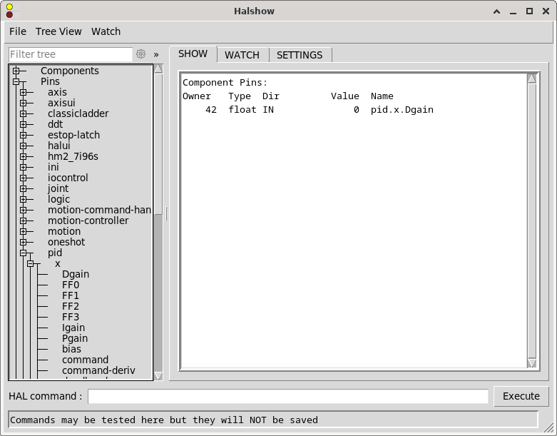
Fig. 27 Halshow tool showing the “SHOW” tab.
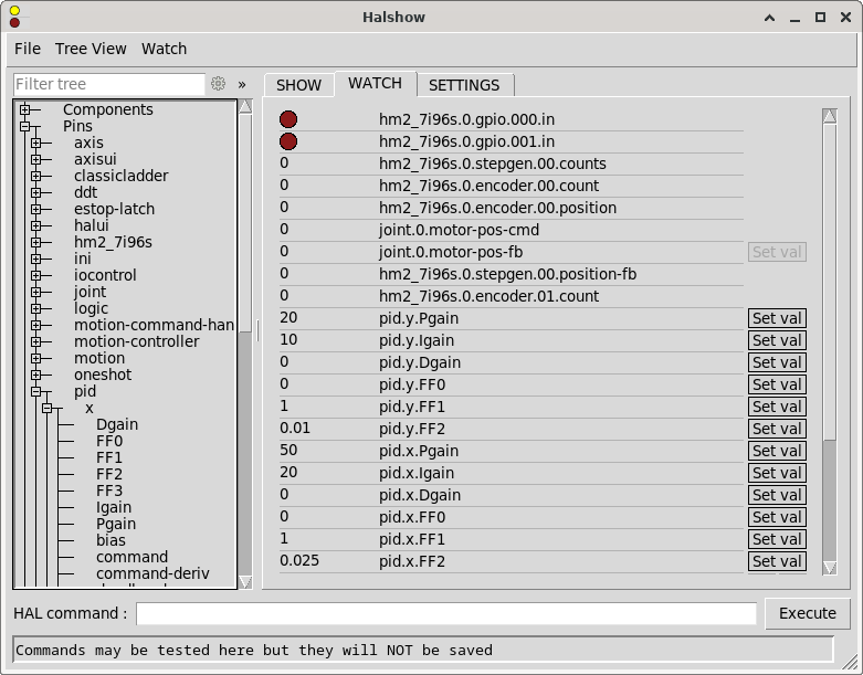
Fig. 28 Halshow tool showing the “WATCH” tab.
3.8.3.3. Halscope
halscope is a graphical tool that provides an oscilloscope for HAL. It allows capturing and displaying the values of pins, signals, and parameters over a period of time. This tool is shown in Fig. 29. The menu allows saving the current configuration or opening a previously saved configuration. When halscope is closed, the configuration is automatically saved to the autosave.halscope file.
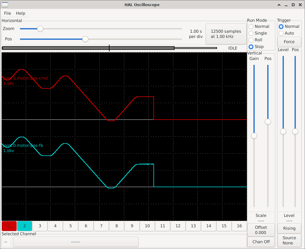
Fig. 29 Halscope tool showing the values of joint.0.motor-pos-cmd (motor position commanded by LinuxCNC) and joint.0.motor-pos-fb (motor position read from the encoder) over time.
You can open the Halscope tool from the AXIS graphical interface by clicking on .
3.8.3.4. Halreport
halreport is a command-line tool that generates a report on HAL connections. The command’s help output is as follows:
Usage:
    halreport -h | --help (this help)
or
    halreport [outfilename]
The generated report displays all signal connections and indicates potential issues. The information included in the report, among other things, is:
System description and kernel version.
Signals and their connected output, input, and input/output pins.
Functions, threads, and
addfcommands corresponding to each pin.Real names for pins that use aliases.
Signals without an output.
Signals without inputs.
Functions not added to threads.
Warnings about components marked as obsolete.
3.8.4. Ladder Logic Programming
LinuxCNC includes the ClassicLadder component, a free implementation of a ladder interpreter published under the LGPL.
Ladder logic, or the ladder programming language, is a method for drawing electrical logic diagrams. Originally conceived to describe control systems using relays, this approach has become a widely used graphical language for programming PLC devices. It derives its name from the fact that programs in this language resemble ladders, with two vertical rails and a series of horizontal rungs between them.
To use ClassicLadder, you must load the classicladder_rt real-time module in HAL and add the classicladder.0.refresh function to the servo-thread thread using the following commands:
loadrt classicladder_rt addf classicladder.0.refresh servo-thread
Once this is done, you can open the ClassicLadder graphical interface with the system command classicladder, or from the AXIS interface by clicking on . The ClassicLadder graphical interface allows you to create ladder logic programs, as well as view the logical status of the different program components. This interface is composed of several windows, as shown in Fig. 30.
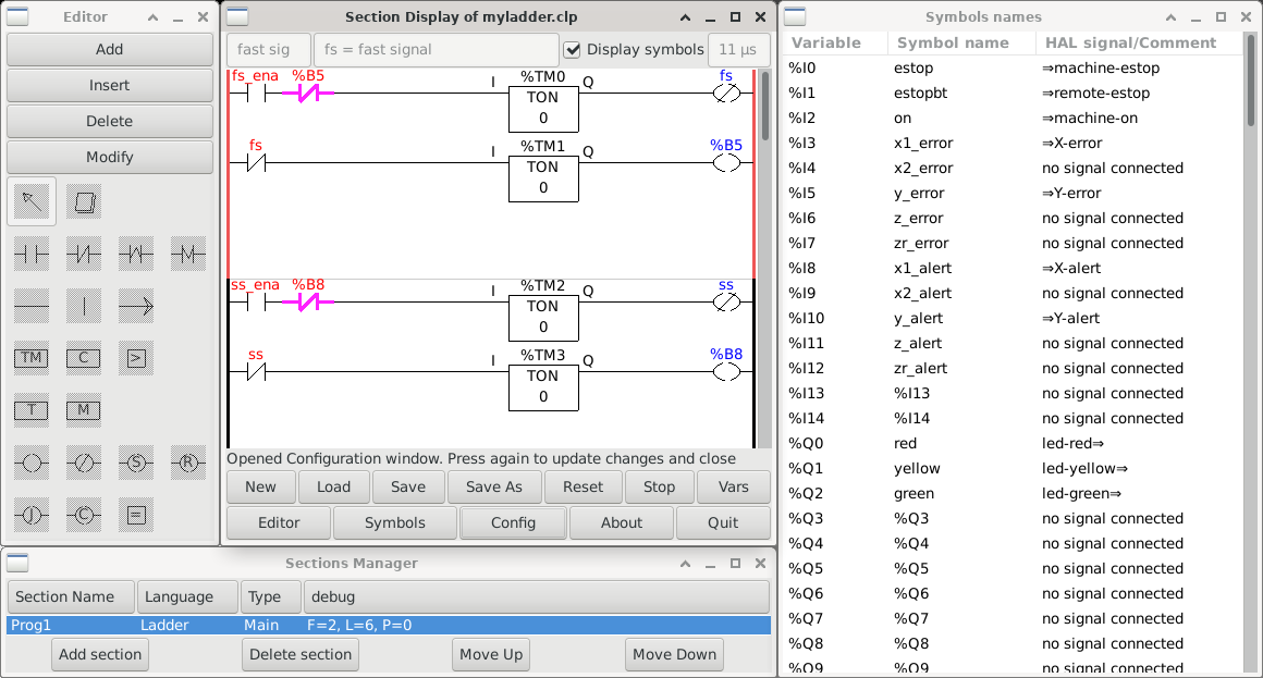
Fig. 30 ClassicLadder graphical interface.
In our testbed setup, ladder logic has been used to program the operation of the LED indicator panel. The program created with ClassicLadder has been saved in the myladder.clp file. To use it in LinuxCNC, it can be loaded with the following HAL command:
loadusr classicladder myladder.clp -nogui
The LinuxCNC user manual [lin23] includes a detailed guide to ClassicLadder. Another good introduction to ClassicLadder is “The Feral Engineer“‘s “Classicladder tutorials” series on YouTube: https://www.youtube.com/playlist?list=PLTYvfbjLClpfAfJSGhZUecgXFwVPY5e09.