2.7. “Oscilloscope” Page
The “Oscilloscope” page, shown in Fig. 13, offers two essential functionalities for adjusting and monitoring motor performance: the internal oscilloscope and the configuration of the motor’s closed-loop control parameters.
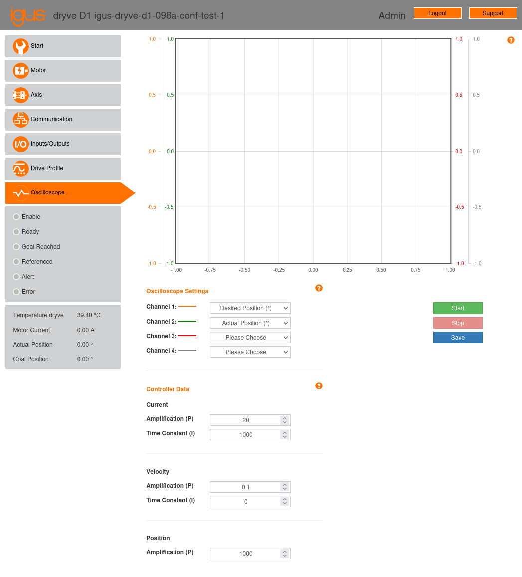
Fig. 13 “Oscilloscope” configuration page of the stepper motor controller.
2.7.1. Oscilloscope
The oscilloscope allows for the simultaneous observation of four channels over a 5-second window, enabling a detailed evaluation of motor behavior in real time. Each channel can monitor one of the following values:
Actual current (A)
Tracking error
Speed (rpm)
Actual position
Desired position
Digital inputs
Analog input 1 (AI 1)
Analog input 2 (AI 2)
2.7.2. Control Parameters

Fig. 14 Closed-loop control of position, speed, and current.
The igus® dryve D1 controller manual does not explicitly describe the control system it implements. We assume that it employs a closed-loop control system with “minor loop feedback compensation” [Wikipediacontributors21, Nis15, GK09]. In this system, the motor’s position, speed, and current are used as feedback signals to precisely and dynamically adjust its position. This control system architecture is commonly used in motor control applications. Its structure, considering the P and I parameters defined by the igus® dryve D1 controller, is shown in Fig. 14, where:
\(R(t)\) is the requested position for the motor at time \(t\).
\(c(t)\) is the current supplied to the motor at time \(t\), used as a feedback parameter for the current controller.
\(p(t)\) is the motor’s position at time \(t\), obtained from the motor’s encoder and used as a feedback parameter for the position controller.
\(v(t)\) is the motor’s speed at time \(t\), obtained as the derivative with respect to \(t\) of the position \(p(t)\) and used as a feedback parameter for the speed controller.
\(e_c(t)\) is the current error, calculated as the output of the speed controller minus the current feedback parameter \(c(t)\).
\(e_p(t)\) is the position error, calculated as \(R(t) - p(t)\).
\(e_v(t)\) is the speed error, calculated as the output of the position controller minus the speed feedback parameter \(v(t)\).
\(\kappa_p\) is the proportional parameter for the position controller.
\(\lambda_p\) and \(\lambda_i\) are, respectively, the proportional and integral parameters for the speed controller.
\(\mu_p\) and \(\mu_i\) are, respectively, the proportional and integral parameters for the current controller.
\(P(\alpha)(t)\) is the impulse response of the proportional block. For an input \(x(t)\), the output of the proportional block at time \(t\) is:
\[x(t) * P(\alpha)(t) = \alpha \cdot x(t)\]\(I(\beta)(t)\) is the impulse response of the integral block. For an input \(x(t)\), the output of the integral block at time \(t\) is:
\[x(t) * I(\beta)(t) = \beta \int_{-\infty}^t x(\tau) d\tau\]
The “Oscilloscope” page provides access to the configuration of the PI controllers parameters. These parameters allow for optimizing motor performance to meet the specific requirements of each task. For igus® motors, by selecting the corresponding motor model in the motor configuration section (see Section 2.2.1), the control parameters will be set to the default values for the chosen motor. In applications involving high speeds, heavy loads, or when noise reduction is critical, fine adjustments to the control parameter configuration may be necessary.
In our testbed setup, we have configured the following parameters for both motors, which have worked well:
Current
Amplification (P): 20
Time constant (I): 1000
Velocity
Amplification (P): 0.1
Time constant (I): 0
Position
Amplification (P): 1000
Note
When configuring the motor control parameters in the “Oscilloscope” page, it is important to consider the following points:
Parameters become effective upon pressing “enter” or unfocusing the corresponding parameter input field.
Parameters require very fine adjustment; an abrupt change in a parameter can cause the corresponding PI controller to become unstable and result in sudden motor movement. In such a case, if the movement limit parameters have been adequately configured (see Section 2.3.2), the controller should stop the motor and report a tracking error.
Setting some parameters to excessively high values could lead to unwanted vibrations and noise in the motors due to oscillations in the PI controller signal. Conversely, setting some parameters to excessively low values could cause the motors to respond slowly to commands issued by the controller.